Ultrasonic sensors are one of the commonly used sensors for obstacle avoidance and ranging in mobile robots. When the sensor is mounted on the robot, it should not be too close to the ground. It is too close to cause interference signals, and it is easy to treat obstacles that can be overcome as insurmountable obstacles. The distance between the two probes of the sensor should not be too far or too close, too far measurement error is too large, too close crosstalk signal is too strong.
The robot hardware system mainly includes: ARM processor, single chip microcomputer, peripheral interface circuit, robot chassis and power supply, among which ARM processor is the core of the upper layer, and 51 single chip microcomputer is the core of the lower layer. The hardware structure block diagram is shown as in Fig. 1.
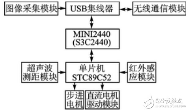
Figure 1 hardware block diagram
The mobile robot adopts the H-bridge control scheme, and the overall control scheme is shown in Figure 2.
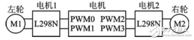
Figure 2 H-bridge control scheme
The motor has 4 PWM outputs for driving the left and right wheels respectively, and 2 motors can control one motor, and the two motors are connected in parallel.
When the L298N chip enable signal ENABLE is high, the output changes with the input, otherwise it is high impedance state, so when soldering, the ENABLE pin and the power pin VS are connected to the power supply VCC.
The specific driving process is as follows: the control chip sends a driving signal through the PWM through the programming, and the PWM output is used as the input of L298N, and the motor is rotated by the L298N conversion output control signal, thereby realizing the driving of the motor.
The PWM output signal can control the DC motor speed. When the duty ratio is increased, the speed is increased; when the duty ratio is decreased, the speed is decreased; when the PWM signal output duty is 0, the motor can be stopped.
When the left wheel stops and the right wheel rotates, the car turns left; when the right wheel stops and the left wheel turns, the car turns right. The positive and negative sequence conversion of the two PWM outputs can control the forward and reverse of the motor, and thus control the forward and backward of the car.
The system software structure is shown in Figure 3.
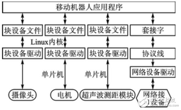
Figure 3 system software structure
Ultrasonic transmitter module design
When the applied signal frequency is equal to the natural vibration frequency of the two piezoelectric wafers, resonance will occur. The center frequency of the ultrasonic sensor used in the subject is 40 kHz. Therefore, in the ultrasonic transmitting circuit, the I/O port is set high by software programming. And set low, generate a 40kHz pulse signal, and output to the transmitting circuit. Because the AT89S51 microcontroller I / O port can provide 20mA sinking current, and the current sinking capacity is small, so 74HC04 to improve its output current, to ensure that the 40kHz pulse signal has a certain power. The schematic diagram of the ultrasonic transmitting module is shown in Figure 4.
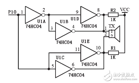
Figure 4 Schematic diagram of the ultrasonic transmitting module
Ultrasonic receiver module design
As shown in FIG. 5, the ultrasonic receiving processing circuit uses the integrated circuit CX20106. When the CX20106 receives a signal corresponding to its center frequency, the 7 pin outputs a low level. The pulse falling edge of the 7-pin output and the infrared sensor ranging signal are connected to the MCU interrupt port.
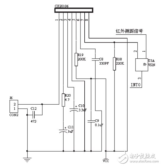
Figure 5 Schematic diagram of the ultrasonic receiving circuit
Reflective infrared sensor detection system design
The infrared ranging circuit is shown in Figure 6. The LM567 can form a low-frequency oscillator as the encoding circuit of the infrared sensing system, that is, using its internal voltage-controlled oscillator to generate low-frequency signals, since R25=10.9kΩ, C25=2200pF, according to The formula f0 =1/1.1RC, the 5-pin output frequency of the pulse signal of 38.91kHz. This pulse signal causes transistor T1 (8050) to operate in a switching state, driving an infrared pulse from the infrared light emitting diode. The use of this method eliminates the signal generation circuit, simplifies the line and debugging work, and prevents the difference between the surrounding environment and the component parameters from being changed to the transmitting and receiving frequency, and realizes the synchronous automatic tracking of the infrared transmitting and receiving working frequencies, so that the circuit The stability and anti-interference ability are greatly enhanced.
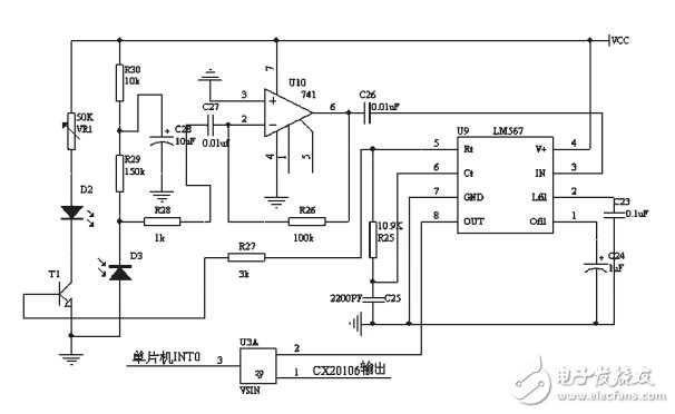
Figure 6 Reflective infrared sensor ranging schematic
Edit Comment : This paper uses the advantages of ultrasonic sensor and infrared sensor to design a mobile robot sensing system based on ultrasonic sensor and infrared sensor. The system uses infrared sensors to compensate the detection dead zone of the ultrasonic sensor, so that the mobile robot has a larger sensing range.
Electronic enthusiasts "Wireless Communications Special Edition", more quality content, download now

Open Air Profile Disc Insulator is an assembly of one or more shells with metallic fittings, Glass Electrical Insulators have means for non-rigid supporting. In operation, Profile Disc Glass Insulator is always connected to insulator string, Suspension Insulator set complete with the fittings is used to carry a line conductor or conductors at its lower end. U70BP-U120BP Profile Disc Toughened Glass Insulator comply with IEC, ANSI standard.
| MAIN DIMENSIONS AND STANDARD PARTICULARS | ||||||||
| Currency Designation | U70BP/146M | U100BP/127M | U120BP/127M | U120BP/146M | U160BP/146M | U160BP/155M | U160BP/170M | U160BP/170M |
| Designation | LXAP1-160 | LXAP-160 | LXAP-210 | LXAP-240 | ||||
| Diameter D,mm | 380 | 380 | 380 | 380 | 420 | 420 | 420 | 420 |
| Spacing H,mm | 146 | 146 | 127 | 146 | 146 | 155 | 170 | 170 |
| Creepage L,mm | 365 | 365 | 365 | 365 | 380 | 380 | 380 | 380 |
| Socket Soupling,mm | 16 | 16 | 16 | 16 | 20 | 20 | 20 | 20 |
| Mechanical Falling Load,KN | 70 | 100 | 120 | 120 | 160 | 160 | 210 | 210 |
| Mechanical Routine Test,KN | 35 | 50 | 60 | 60 | 80 | 80 | 105 | 105 |
| Wet Power Frequency withstand voltage,KV | 45 | 45 | 45 | 45 | 50 | 50 | 50 | 50 |
| Dry Lighting Impulse withstand voltage,KV | 90 | 90 | 90 | 90 | 95 | 95 | 95 | 95 |
| Impulse Puncture Voltage,PU | 2.8 | 2.8 | 2.8 | 2.8 | 2.8 | 2.8 | 2.8 | 2.8 |
| Power Frequency Puncture Voltage,KV | 130 | 130 | 130 | 130 | 130 | 130 | 130 | 130 |
| Radio Influence Voltage,μv | 50 | 50 | 50 | 50 | 50 | 50 | 50 | 50 |
| Corona Visual Test,KV | 18/22 | 18/22 | 18/22 | 18/22 | 18/22 | 18/22 | 18/22 | 18/22 |
| Power Frequency Electric arc voltage,KV | 0.12s/20ka | 0.12s/20ka | 0.12s/20ka | 0.12s/20ka | 0.12s/20ka | 0.12s/20ka | 0.12s/20ka | 0.12s/20ka |
| Net Weight per unit,KG | 5.3 | 5.2 | 5.3 | 5.4 | 7.2 | 7.2 | 7.3 | 7.3 |


We warmly welcome friends both domestic and abroad to visit our company, for more details about Glass Insulator , if you have any questions, please contact with us directly.
Open Air Profile Disc Insulator
Glass Electrical Insulators,Profile Disc Glass Insulator,Profile Disc Toughened Glass Insulator,Open Air Profile Disc Insulator
FUZHOU SINGREE IMP.& EXP.CO.,LTD. , https://www.cninsulators.com