In the amplifier market, depending on the type of flight, the type of power amplifier is not nearly the same. There are three main categories of classification for power amplifiers: conductive methods, functions, and uses. There are also different categories under each major type. Today, the author analyzes the circuit diagrams and principles of various types of power amplifiers in detail.
Classification method: Different conductive methods
Classification: Power amplifiers can be divided into Class A amplifiers (also known as Class A), Class B amplifiers (also known as Class B), Class A Class B amplifiers (also known as Class AB) and Class D amplifiers (also known as Class D).
Class A power amplifier (A power amplifier) ​​principle:
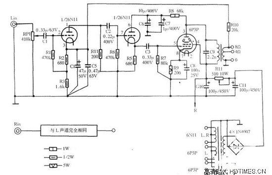
Class A quiescent current is large, positive and negative half weeks are the current of a tube is changing, there is no distortion, low efficiency, good sound quality. The operating point of the Class-A amplifier's output transistor (or tube) is at the midpoint of its linear portion. Regardless of the signal level, the current it draws from the power supply is always constant, and it is inefficient. When used for audio amplification, the actual efficiency cannot exceed 25% due to the continuous change of signal amplitude, and it can be operated by single tube or push-pull.
Class A power amplifier (A type power amplifier) ​​circuit diagram:
Class B amplifier (Class B amplifier) ​​principle:
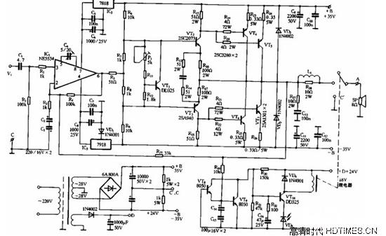
Class B amplifier biases push-pull transistors (or tubes) in the low-current state when there is no drive signal. When a drive signal is applied, the current in one pair of tubes rises in one half cycle, and the other Only the tube tends to cut off. In the other half of the cycle, the situation is reversed. Since the two tubes work in rotation, the push-pull circuit must be used to achieve a complete signal waveform.
Class B amplifier (B power amplifier) ​​circuit diagram:
Class A and Class B Power Amplifier (AB Class Power Amplifier) ​​Principle:
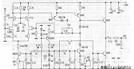
Class AB power amplifiers (Class AB) also become Class A and Class B power amplifiers. It is a design that is compatible with the advantages of Class A and Class B power amplifiers. When there is no signal or the signal is very small, the positive and negative channels of the transistor are always on. At this time, the power is lost. However, there is no serious type A power amplifier. When the signal is in positive phase, the negative phase channel is normally open before the signal becomes strong, but the signal is strong and the negative channel is closed. When the signal is negative, the positive and negative channels work just the opposite.
Class A amplifier (AB class power amplifier) ​​circuit diagram:

Class D amplifier (class D amplifier) ​​principle:
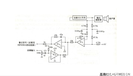
A Class D amplifier is an amplification mode in which the amplifying element is in a switching state. The amplifier is in the off state when no signal is input, and no power is consumed. During operation, the transistor is brought into saturation by an input signal. The transistor is equivalent to a switch that is turned on, and the power supply and the load are directly connected. The ideal transistor does not consume power because there is no saturation voltage drop, in fact the transistor will always have a small saturation voltage drop and consume some power. This kind of power consumption is only related to the characteristics of the tube, and has nothing to do with the size of the signal output, so it is particularly advantageous for ultra-high power applications.
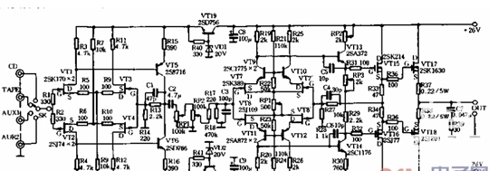
D amplifier (D amplifier) ​​circuit diagram:
Classification method: different functions
Category: Preamplifiers (also known as preamps), power amplifiers (also known as post stages), and integrated amplifiers
Preamplifier principle:
After the signal enters the front stage through the input/output terminal, the circuit board or the isolated signal line is used to guide the signal to the switch. The switch is responsible for switching the input source. Through the use of several switchers, the output of the recording can also be controlled. The type of the source, the signal after the switch, then enter the left and right channel balance control potentiometer, audio balance potentiometer used for the special MN type.
Preamplifier circuit diagram:
Power amplifier principle:
Power amplifier circuit diagram: 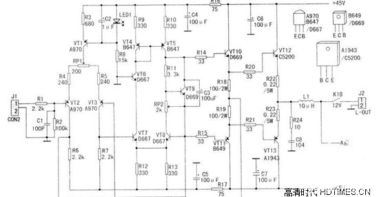
Combined amplifier principle:
A combined amplifier refers to an amplifier that combines pre-amplification and power amplification in one chassis. Therefore, the above two principles, combined amplifiers, have such a principle.
Combined amplifier circuit diagram:
Classification method: different usage
Classification: can be divided into AV power amplifier, Hi-Fi power amplifier
AV amplifier principle:
AV amplifiers are amplifiers designed specifically for home theater use. They typically have more than four channels and surround decoding, and they have a display. The main purpose of this type of amplifier is to truly create the sound environment of the film and let the audience experience cinematic effects.
AV amplifier circuit diagram:

Hi-Fi amplifier principle:
The HIFI amplifier is an amplifier designed for reproducing the true nature of music with high fidelity. It is generally a two-channel design and has no display. "HI-FI amplifier" is the amplifier of our enthusiasts, and its output power is generally below 2X150 watts. The design is based on the principle of “a beautiful tone and a high degree of fidelityâ€.
HiFi power amplifier circuit diagram:
