With the rapid development of the automotive industry, there are more and more electronic control units on the body. Traditional body harnesses not only increase manufacturing costs, but also reduce system reliability and maintainability. As a result, the car body bus came into being. The body bus design not only simplifies the wiring, saves manufacturing costs, improves reliability, but also saves system maintenance costs. The vehicle anti-theft alarm module is part of the body control unit (BCM). Because it has low real-time and speed requirements for bus communication, it is connected to the low-speed bus LIN.
LIN bus
The LIN bus is mainly used for low-speed systems that do not require CAN performance, speed and complexity. It is a low-cost serial communication network that uses a master node and several slave nodes, based on a common UART/SCI hardware interface. The maximum rate can reach 20kb/s.
This article refers to the address: http://
The LIN bus transmits data through message frames. A complete message frame includes a frame header and an information response. The header includes an interval field, a sync field, and a marker field. The interval field consists of a persistent dominant level (0) of at least 13 bits, marking the beginning of a message frame during a data communication. The sync field contains clock synchronization information, and its format is 0x55. After all slave nodes correctly receive the sync byte field, the baud rate of the data to be sent by the host node is accurately calculated, and the baud rate is used as the next step or The baud rate setting value of the data is received, thereby synchronizing the clock between the slave node and the host node. The flag field defines the content and length of the message. The message response is sent by the host node or the slave node according to the information of the flag field, and is composed of 2, 4 or 8 bytes of data and a 1-byte checksum. The verification is obtained by calculating all the bytes of the data for the correctness of the data of the receiver.
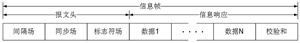
Figure 1 complete LIN information frame
Function description The vehicle anti-theft alarm module is a slave node of the body control module. The main functions are as follows: one is to maintain communication connection with the BCM and report the status information of the anti-theft alarm module; the second is to receive the command of the body control module and drive The horn emits an alarm sound; the third is to monitor whether the power line, ground line and LIN line between the connection burglar alarm module and the BCM are cut off and an alarm sounds.
Implementation plan
1 Device Selection The two main components of the system are the LIN transceiver and the microprocessor. Since the burglar alarm module is a battery-powered LIN node, it is necessary to consider low-power devices when selecting devices. The LIN transceiver selects the TJA1020, which is the physical media connection between the body controller and the intrusion alarm module, and is the interface between the LIN master/slave protocol controller and the LIN transmission medium. The transmit data stream of the protocol controller input pin TXD is converted to a bus signal by the LIN transceiver, and the level flip rate and waveform are limited to reduce electromagnetic radiation. The receiver of the TJA1020 detects the data stream on the LIN bus and passes it to the protocol controller via the RXD pin. The TJA1020 features a low-power management mode that consumes little current in sleep mode and reduces power consumption in error mode. Therefore, the TJA1020 is ideal for battery-powered LIN nodes such as the Burglar Alarm Module. The system uses STMicroelectronics' 8-bit microprocessor STM8S105K4 as the master microcontroller. When running with the internal 128kHz clock, the static power consumption can be as low as 0.6mA. Meets the system's low power requirements while providing the LIN controller and battery charge detection 10-bit ADC function.
2 Information frame classification and system state definition The communication information frame between the body control system and the burglar alarm module is defined as follows:
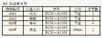
The wake-up command is used to wake the system from sleep to the unarmed state, and the sleep command is used to command the system to go to sleep. The contents of the command information frame include fortification, defense, alarm commands, and definitions of alarm status such as alarm period, number of times, and so on. The state transition of the system is shown in Figure 2.
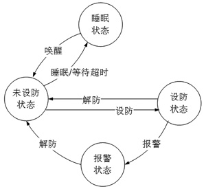
Figure 2 state transition diagram
3 basic block diagram system basic block diagram shown in Figure 3, the system and external interface has three, LIN line, power line and ground line. The vehicle battery supplies power to the rechargeable battery, the TJA1020 and the MCU, respectively, wherein the function of the rechargeable battery is to provide the system with the power required for the alarm when the vehicle battery power is cut.
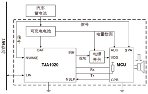
Figure 3 basic block diagram of the system
Initially, the TJA1020 is in a sleep state and shuts off power to the MCU through the INH pin, at which point the state of the system is defined as sleep. Connecting the car battery is equivalent to the TJA1020's NWAKE pin to generate a level change, which triggers the external interrupt wake-up of the TJA1020, while the TJA1020's Tx pin generates a strong pull-down. When a remote LIN message frame wakes up the TJA1020, the Tx pin will generate a weak pulldown. After the TJA1020 is woken up, the MCU is powered on by the INH pin to make the MCU start working, and the system enters the unarmed state.
In the unarmed state, the MCU detects whether there is a car battery power supply signal through the GPA port. If there is no power supply signal, the system will make the TJA1020 enter the sleep state by connecting the GPB pin of the NSLP after a certain time, and the TJA1020 will be closed by the INH pin. The power supply of the MCU returns to sleep. When the car battery power supply exists, if the LIN sleep information frame is received, the system also goes to sleep.
When the system is in the non-sleep state, it can be converted between the unarmed state, the armed state, and the alarm state by receiving the LIN command information frame of the BCM. When the system is in the armed state and alarm state, it will not go to sleep.
4 software flow system software mainly includes the program to realize the communication between the single chip and the LIN bus and the main program of the single chip to control the burglar alarm horn. To ensure real-time communication, the system uses high-priority interrupts to receive signals on the LIN bus. In order to ensure the real-time nature of the system, in addition to some simple judgments and data reception during interrupt processing, other parts are processed in the main program.

Figure 4 main program flow chart
Once a valid dominant level appears on the bus, the controller immediately switches to the high priority interrupt handler function, first determining whether the interval field is sent by the host node, and if it is an interval field, receiving the sync field and the flag field, if not the synchronization The field then exits waiting for the next interruption. After receiving the correct identifier, if the identifier requires the system to send information, the system sends the data field and the checksum field, and after the transmission is completed, it starts to wait for the next frame of data. If the identifier does not require the local device to transmit data, it will receive the subsequent data field and the checksum field. In the main program, it is judged according to the identifier whether the received data is valid for the local device. If it is valid, it will be processed accordingly. It is discarded, and after processing is completed, it waits to receive the next frame of data.
Innovation of MCU control system was adopted to realize stepless, four color temperature of light output, single control/group control, timer switch, smartprofiles, ect
Wireless control, easy to install. 86 controller, light sensor is compose of simple control system can compatible with our remotecontrol.
CCT Changeable & Dimmable Downlight
Dimmable LED Downlights,CCT Changeable Downlight,CCT Dimmable Downlight,Cut Out 160-180mm Downlight
SHENZHEN KEHEI LIGHTING TECHNOLOGY CO.LTD , http://www.keheiled.com