There are many reasons for loss in the distribution network, of which line loss and network loss are the two most important. This paper first introduces the theoretical calculation method of line loss and network loss, and then proposes measures to reduce the distribution network from multiple angles.
First, loss analysis
1.1 theoretical line loss calculation method
The theoretical calculation methods of line loss mainly include rms current method, average current method, maximum current method, and maximum load loss hour method. The average current method and the maximum current method are derived from the rms current method, and the maximum load loss hour method is mainly applicable to the planning and design of the power grid. A more representative traditional method is the rms current method.
The physical concept of the rms current method is the loss of electrical energy produced by the rms current flowing through the line, which is equivalent to the electrical energy consumed by the actual load during the same period. Its calculation formula
The application of the rms current method to calculate the line loss of 10kV distribution lines mainly has the following problems:
1Because the rated capacity of the distribution transformer can not reflect its actual power consumption, for the distribution transformer without the measured load record, the calculation of the RMS current core proportional to the rated capacity of the transformer is generally not completely in line with the actual load. Situation.
2 The root mean square current of each branch line and each line segment is obtained by adding and subtracting the root mean square current algebra of each load, and in general, the load curve shape and power factor of each load point of the actual system are different, so It is not reasonable to use the root mean square current of the load to add and subtract directly to obtain the rms current of each branch line and each line segment. This is the main cause of the error.
1.2 network loss calculation method
1.2.1 rms current method
The rms current method is simple and easy to master. It is quite effective for calculating the power loss of local power grids and individual components or when only the ammeter is installed at the line, especially in the calculation of power loss of 0.4-10kV distribution network. Among them, the method is easy to popularize and popularize, but the disadvantage is that the workload of load surveying and recording is huge, it needs 24h monitoring, the accuracy is poor, and the calculation accuracy is small. Due to the lack of automatic feedback on the user's electricity information, the current power system operation management in China The calculations bring difficulties, so the scope of application of the law has limitations.
1.2.2 node equivalent power method
The node equivalent power method is simple and has a wide range of application. When the theoretical analysis of the network loss of the operating grid is performed, the operating data based on the meter is derived from the metered energy meter. Even if the shape of the specific load curve is not known, the calculation result can be calculated. The maximum possible error is estimated, and the accuracy level of the electric energy meter itself is higher than that of the current meter, and there is a strict periodic calibration system. Therefore, the original data such as power generation and load 24h power and other operating parameters are relatively accurate and easy to obtain. This method greatly simplifies the process of collecting and sorting the original data. In essence, this method converts the calculation problem of power loss into the calculation problem of power loss, or further converts it into the power flow calculation problem. It is accurate and easy to implement, so it can be used for the calculation of any network line loss when the load power changes little, and the well is satisfied. However, the disadvantage is that the actual calculation process of the method is time consuming and laborious, and the calculation result is low in accuracy. Because the method only approximates the system state by taking the node power curve of the actual continuous change as the power curve of the stepwise change or checking the shape coefficient of the load curve to obtain the equivalent power of the node.
Second, the reduction measures
1. Simplify the voltage level of the power grid. Reduce the repeated substation capacity. The urban power grid reconstruction project requires: only four transformations from 500kV to 380/220V. In addition to the northeast part of the power grid using 500kV, 220kV, 63kV, 10kV, 380/220V five levels. Other power grids use five levels of 500 (330) kV, 220 kV, 110 (or 35) kV, 10 kV, and 380/220V. That is, one of the high-voltage distribution voltages is selected between 110kV or 35kV as the development direction. Non-development networks use phasing out or boosting measures.
2. Improve transmission capacity and optimize utilization of power generation resources
Building new AC or DC transmission lines, upgrading existing lines and bringing existing lines closer to their thermal stability limits are the three main ways to increase transmission capacity.
When an overhead transmission line is used to transmit power over long distances, the efficiency of the high voltage direct current transmission line (HVDC) is higher than that of the high voltage alternating current transmission line. At the same voltage level, the transmission capacity of the HVDC system is 2 to 5 times that of the AC line; and when the transmitted power is the same, since the DC line does not transmit reactive power, the loss of the converter is only 1.0% of the transmission power. ~1.5%, so the total loss of the HVDC transmission system is less than the AC system.
Increasing the transmission capacity of existing lines can increase the voltage level, increase the cross-sectional area of ​​the conductors, and the number of split conductors per phase, or use high-temperature resistant wires. Recent advances in high temperature wire technology have provided an effective way to reduce the thermal stability limits of medium and short distance transmission lines. The current transmitted by the high-temperature wire transmission line is 2 to 3 times that of the ordinary wire transmission line (for example, the aluminum-clad steel reinforced wire), and its cross-sectional diameter is the same as that of the ordinary wire, and does not increase the burden of the support structure such as the tower. In many cases, the operating capacity of a transmission line is much lower than the thermal stability limit of the line due to voltage constraints, stability constraints, and constraints on system operating constraints. Many technologies have been invented for how to increase the utilization of transmission capacity. For example, when a "parallel branch current" or "loop current" problem occurs, phase modulators are often used to eliminate the thermal stability limitations of the branch. Series capacitor compensation is another common method for increasing transmission capacity in long-distance high-voltage AC transmission lines. Nowadays, people have developed a series of equipment using high-power power electronics technology, collectively referred to as flexible AC transmission equipment, which enables people to make better use of the capacity of related equipment such as transmission lines, cables and transformers. It is estimated that the promotion and application of flexible AC transmission equipment can increase the maximum transmission capacity of lines that are now limited by voltage constraints and stability constraints by 20% to 40%.
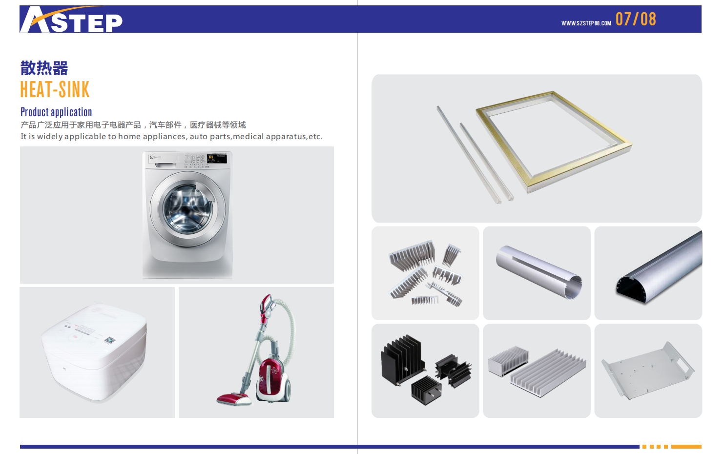
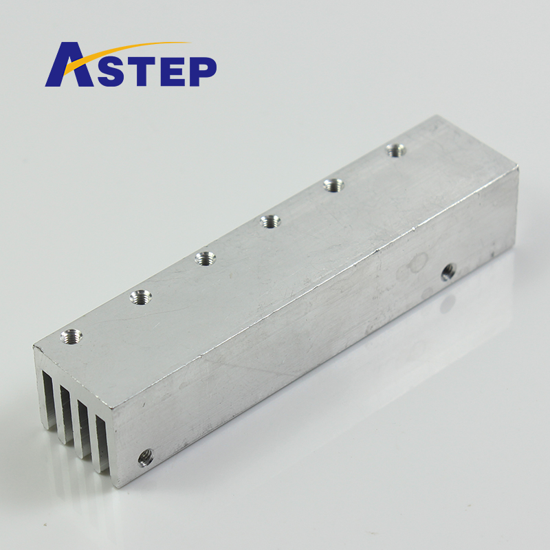
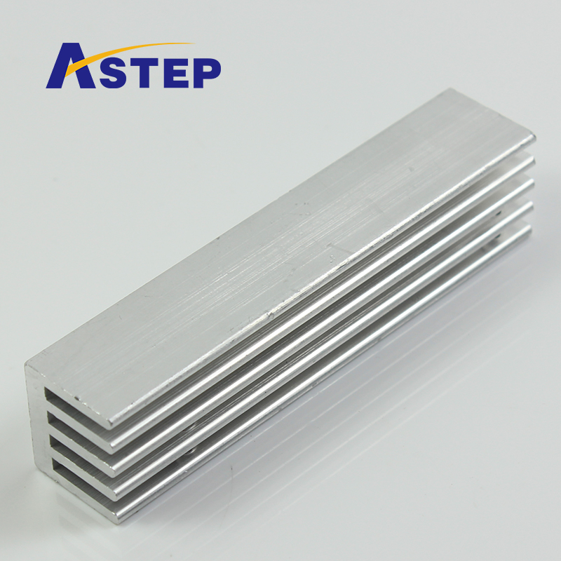
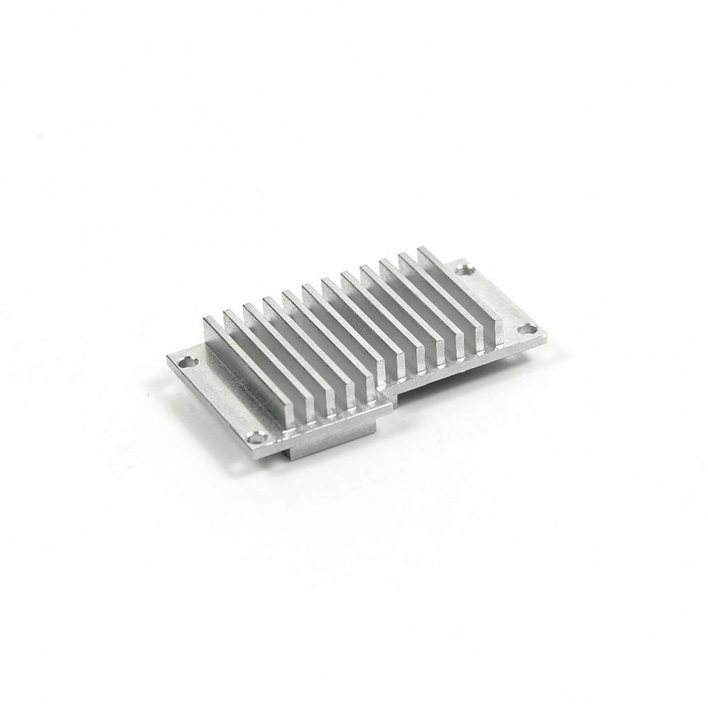
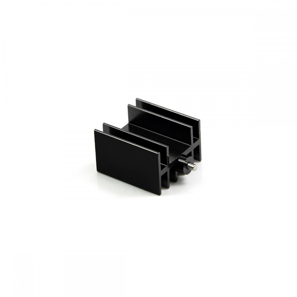
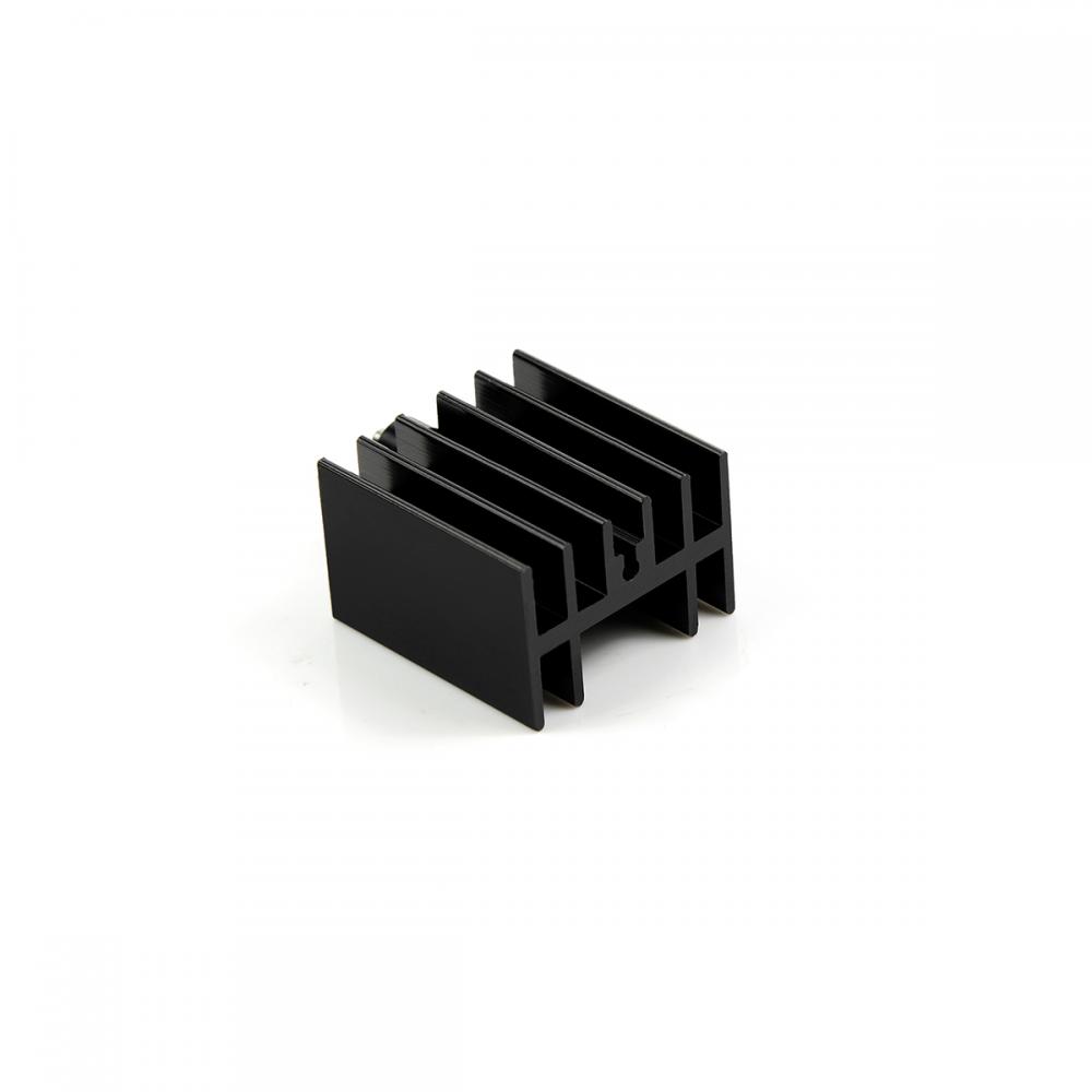
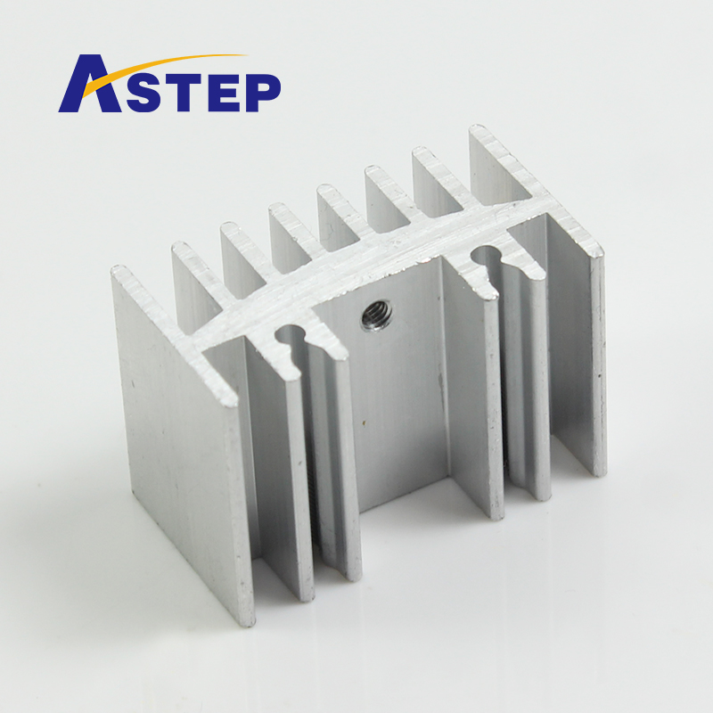
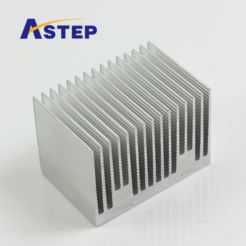
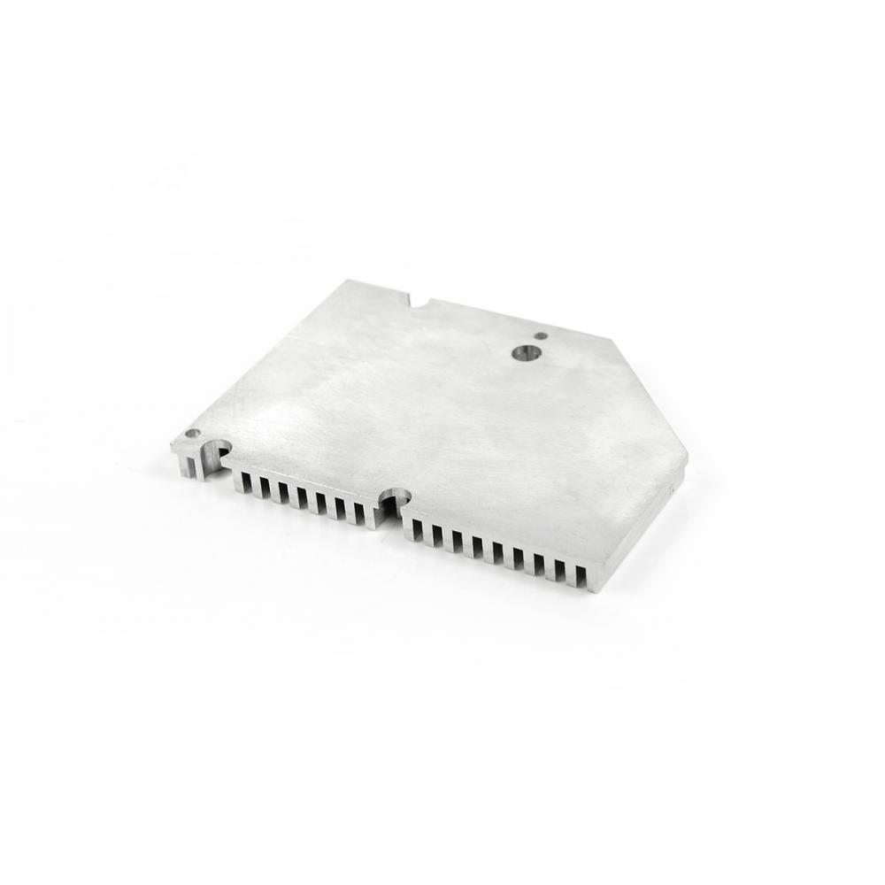
Heat Sink is widely applicable to home appliances, auto parts, medical apparatus,etc.
1. Grade: AL6063
2. Size: T5
3. Standard: DIN 315
4. Certification: ISO9001, ISO14000,IATF16949
|
Product Name
|
Best stainless steel wing nut anchor bolt for construction fastener
|
|
Material
|
Aluminum alloy
|
|
Color
|
Customized Color
|
|
Standard
|
DIN GB ISO JIS BA ANSI
|
|
Grade
|
AL6063
|
|
Brade
|
Rock
|
|
Thread
|
coarse, fine
|
|
Used
|
building industry machinery
|
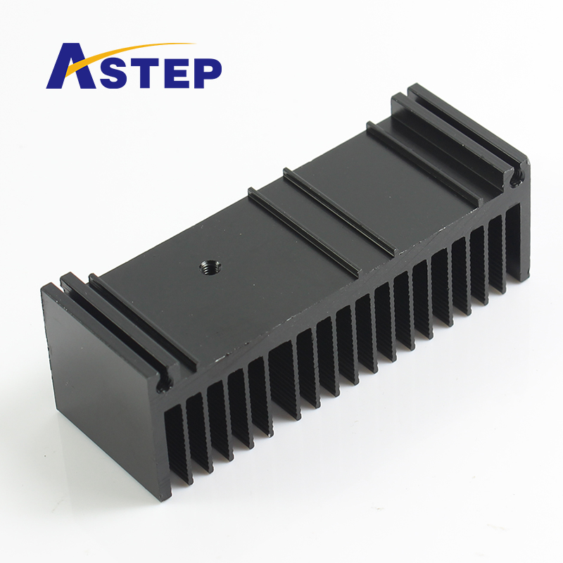
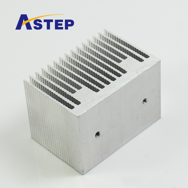
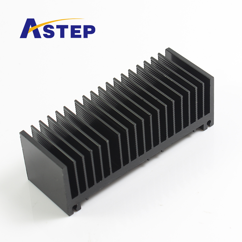
Heat-Sink,Heat Radiator Sink,Aluminum Heat Radiator,Etruded Heat Sink
Shenzhen Jedver Smart Lighting Co., Ltd. , http://www.jederwell.com