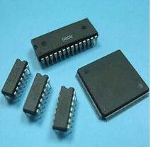
IC is a general term for semiconductor component products. ICs can be divided into digital ICs, analog ICs, microwave ICs, and other ICs.
Digital IC is an IC that transmits, processes, and processes digital signals. It is the most widely used and fastest-developing IC in recent years. It can be divided into general-purpose digital ICs and dedicated digital ICs.
EDA tools play an important role in the digital IC design process. IC design has always been a combination of EDA tools and the human brain. As ICs continue to develop toward high integration, high speed, low power consumption, and high performance, it is impossible to complete the design without high reliability computer-aided design means.
First, design input (design input)
Use vhdl or verilog language to complete the logical function description, generate hdl code
1, language input tool:
SUMMIT VISUALHDL
MENTOR RENIOR
2, graphic input:
Composer(cadence);
Viewlogic (viewdraw)
Second, functional simulation (funcTIonal simulaTIon)
Perform the previous logic simulation of the hdl code to verify that the function description is correct
1, digital circuit simulation tools:
Verolog: CADENCE Verolig-XL
SYNOPSYS VCS
MENTOR Modle-sim
VHDL : CADENCE NC-vhdl
SYNOPSYS VSS
MENTOR Modle-sim
Third, logic synthesis (synthesis tools )
The logic synthesis tool can convert the design idea vhd code into a gate-level circuit corresponding to a certain process; the gate delay that is not considered in the primary simulation is counter-marked to the generated gate-level netlist, and the return circuit simulation phase is performed. Re-simulation. The netlist generated by the final simulation result is called a physical netlist.
Comprehensive tools:
CADENCE Builtgates Envisia Ambit
SYNOPSYS Design Compile Behavial Compiler
Fourth, static timing analysis (staTIc TImming analyze)
Synopsys Prime Time
Power analysis WattSmith
Five, layout generation and automatic layout (auto plane & route)
Generate a specific circuit layout of the netlist
Layout tool: CADENCE Dracula, Diva
Sixth, physical verification (physical validate) and parameter extraction (LVS)
The most famous and powerful ASIC design is cadence's DRECULA, which can complete the process tools from DRC (design rule check), ERC (electrical characteristic check) to LVS (parasitic parameter extraction) at one time:
CADENCE: DRECULA
AVANTI : STAR-RC
Timing convergence, power consumption, and area problems that occur during the verification process should be returned to the front-end code input for re-modification, re-simulation, re-synthesis, and verification. Generally, it must be repeated several times before finally being sent to the foundry factory.
LED Flexible Light Strip
Kindwin Technology (H.K.) Limited , https://www.ktlleds.com