1 Introduction to the speed sensor performance test platform
This article refers to the address: http://
The speed sensor is a key component of an electronically controlled car. Its performance is directly related to engine idle speed and transmission control. Therefore, it is necessary to conduct comprehensive and rigorous testing of its performance. This series of performance tests depends on a stable and efficient test platform. The traditional test platform usually adopts a three-level system structure consisting of a test device, a test console computer, and a background management computer, as shown in FIG.
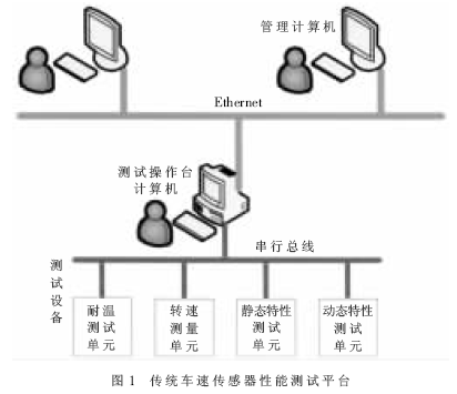
In this test platform, the test equipment generally only provides serial communication interfaces (such as RS-232, RS-485, etc.), and cannot directly access the local area where the management computer is located (such as the most commonly used Ethernet). Therefore, the entire system must connect the upper layer LAN and the underlying serial bus network through a test console computer to ensure the smooth uploading of test data (various performance indicators data) and test operation commands (such as vehicle speed sensor temperature test, dynamic / Accurate release of static characteristic test). To this end, not only must the test console computer workstation be added, but also various serial port communication cards, Ethernet network cards and corresponding board drivers must be installed to develop the measurement and control software including the serial port communication module and the Ethernet communication module. It can be seen that due to the incompatibility between the communication interface and the protocol, the traditional vehicle speed sensor performance test platform not only has high software and hardware investment cost, complex system structure, large debugging and maintenance workload, but also data transmission between the management computer and the test equipment. The transfer process is too complicated.
2 Serial port-Ethernet bridge based test platform
Through the research on the test platform shown in Figure 1, it is found that the root cause of high cost, complicated structure and complicated intermediate processing process is the incompatibility between the underlying test equipment and the upper layer LAN communication interface and protocol. Generally speaking, the amount of data to be transmitted by the underlying test equipment is very small, and most of them only provide serial ports with short communication distance and low cost (such as RS-232, RS-485); while the upper layer LAN mostly adopts Ethernet. Therefore, for such applications, a microprocessor-based embedded serial port-Ethernet bridge can be developed to implement protocol conversion [1], and various test devices supporting only serial ports can be directly connected to the Ethernet to realize each The seamless connection between the test equipment and the management computer LAN simplifies the data transfer process.
The structure of the vehicle speed sensor performance test platform after the introduction of the embedded serial port-ether bridge is shown in Fig. 2.
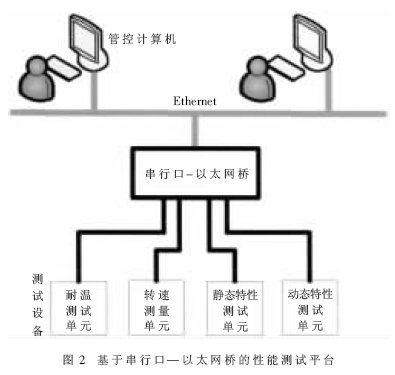
Compared with the traditional test platform shown in Figure 1, the serial port-ether bridge under the new test platform is responsible for the protocol conversion between the serial port test device and the Ethernet (that is, the serial frame data and Ethernet are completed at the bottom layer). The format conversion of frame data) realizes a seamless connection between each test device and Ethernet, which simplifies the data transmission process. The tester can directly test various performance indicators of each test device by directly issuing various test commands through the upper management computer at the remote end; and the measured data can be directly transmitted from each test device to the background management computer for processing; So that the background management computer can complete the front-end test equipment control and background data processing (such as statistical analysis of data reports, graphical curve display and database update) in a multi-tasking manner, and become an integrated management and control workstation in the platform, eliminating the original platform. Test bench computer workstations, testers do not have to visit the site to carry out various test operations, greatly reducing the intensity of work. In this way, not only the system cost is greatly reduced, the volume is greatly reduced, the structure is simpler, and the front-end test control and background data processing are concentrated on one computer, which realizes the integration of management and control, saves human resources, and makes the system The hardware and software resources are utilized to the maximum extent.
3 serial port - Ethernet bridge design
Through the comparison of the old and new test platforms, it can be seen that the test device and the background management computer are basically the same in performance and cost. Therefore, the performance and cost of the new test platform depends largely on the performance and cost of the newly introduced embedded serial port-Ethernet bridge. At present, most of these network devices in the embedded product market are developed based on high-end microprocessors and real-time operating systems. They are expensive and provide only one or two serial ports. It is not suitable for multiple serial ports. Equipment is centrally connected to the Ethernet, while at the same time controlling the cost of the application. Based on this specific application requirement, this paper designs a low-cost embedded serial port-Ethernet bridge that provides multiple serial ports on an 8-bit microcontroller platform. The hardware and software system design is described below.
3.1 Hardware System Design
To realize the function of the serial port-Ethernet bridge used in this system, it is necessary to perform Ethernet access of multiple serial port devices, and mutual conversion between serial communication protocol and Ethernet communication protocol. Therefore, the hardware circuit design mainly includes the design of multiple serial port circuit modules and Ethernet interface circuit modules. In this paper, the hardware system solution uses ST industrial-grade SoC-type microcontroller uPSD3254 and Realtek's high-performance Ethernet controller RTL8019AS two core devices for circuit design. The hardware system design is shown in Figure 3.
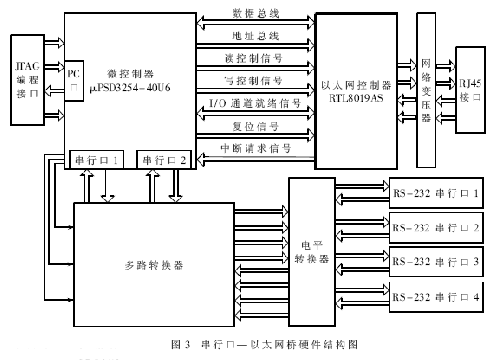
Among them is an enhanced high-speed microcontroller with SoC features consisting of 8051 core modules and PSD modules. The crystal frequency can be up to 40MHz. The PSD module in the chip provides users with a wealth of configurable memory resources (256KB main Flash, 32KB Flash and 32KB SRAM), flexible DPLD address decoding circuit and 3000-gate CPLD module circuit. The on-chip hardware watchdog greatly improves the system reliability. The chip comes with a JTAG interface to support ISP in system programming, which facilitates program debugging and downloading. The RTL8019AS is a very mature ISA bus-based, NE2000-compatible cost-effective 10M. The Ethernet controller itself can complete the Ethernet protocol processing, and only needs simple connection with the microcontroller to realize Ethernet communication. In addition, the hardware circuit also includes a few peripheral devices such as a MAX232 level shifter and a 20F001N network filter. The whole hardware system is composed of only 4 or 5 chips, and the structure is simple and compact, high reliability and low cost. The specific design of the hardware circuit is given from three aspects below.
3.1.1 PSD module configuration design
The PSD module of the microcontroller uPSD3254 greatly simplifies the design of the hardware circuit. The two large-capacity Flash and SRAM (supporting backup battery) provided by the user itself eliminate the need for external program/data memory expansion. At the same time, the DPLD sub-module in the PSD module provides flexible address decoding for Flash and SRAM. The CPLD sub-module allows users to design some simple combined/sequential logic circuits. The design of the PSD module is configured as follows according to the specific application requirements:
(1) The main Flash sector 0 (fs0) is arranged in the 0000H to FFFFH space of the program memory;
(2) The main Flash sector 1 (fs1) is arranged in the 8000H to 7FFFH space of the program memory;
(3) SRAM (rs0) is configured in the 0000H to 7FFFH space of the external data memory;
(4) The PA port and PB port of the CPLD are designed as two multiplexers respectively for channel switching during serial communication.
3.1.2 Serial Port Expansion Design
As can be seen from Figure 2, four test devices that only support the serial port in the vehicle speed sensor performance test platform (tested for temperature resistance, speed, sensor static characteristics and dynamic characteristics, respectively) must be connected to the embedded serial port-Ethernet. Bridge, and the microcontroller? PSD3254 itself provides only two serial ports (uart0, uart1), so serial port expansion is necessary. A simple extension method is to use a microcontroller I / O port control multiplexer (such as CD4052) for serial port expansion (Figure 3), to achieve point-to-multipoint time-sharing serial port communication. According to the I/O port resources of the microcontroller, the system can expand up to 32 serial ports according to this method. According to this idea and combined with the specific application requirements of the test platform, two alternative multiplexers are designed by using the CPLD module of uPSD3254, which not only expands two serial ports into four (uart00, uart01 and uart10, uart11). ), and the multiplexer chip is omitted. In addition, the level shifter implements TTL-RS232 level conversion, which provides four standard RS-232 serial ports for four test devices for access to the serial port-Ethernet bridge.
3.1.3 Ethernet interface design
The Ethernet interface is the key to hardware circuit design. Because the RTL8019AS is an Ethernet controller based on the ISA bus PC motherboard, its hardware circuitry is very different from the general approach when interfacing with an 8-bit microcontroller (see Figure 3). The following is the specific circuit design from the RTL8019AS Ethernet controller [1] its own function configuration, the bus interface between the microcontroller and the interface with the network medium.
(1) RTL8019AS function pin settings
The RTL8019AS provides three modes of operation: PnP plug-and-play, jumper-free, and jumper. Since the 8-bit microcontroller cannot support the PnP mode of operation, the jump-free mode requires a dedicated serial E2PROM 93C46 to store the corresponding operating parameters, so the jumper mode is selected. In this way, the RTL8019AS interrupt, I / O port address, network interface type selection, etc. are completely dependent on the state of the function pins shown in Table 1.
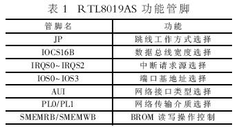
The JP pin is connected to the high level to make the chip work in the jumper mode. The IOCS16B pin is connected to the low level to select the 8-bit data bus. The IRQS0 to IRQS2 are connected to the low level to select the INT0 as the interrupt request source, and the IOS0 to IOS3 are connected to the low-level selection chip. The /O port base address is 300H, AUI, PL0, and PL1 are connected to the low level to select the BNC network interface and the 10Base-T twisted pair transmission medium respectively, and the SMEMRB/SMEMWB is connected to the high level to shield the BROM read and write operations.
(2) Bus interface of RTL8019AS and microcontroller
The interface between the RTL8019AS and the microcontroller is shown in Figure 4.
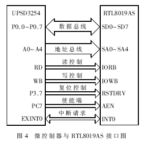
There are several points for the above bus interface: 1Because in the 8-bit microprocessor system, only need to operate the 32 I/O port addresses of the RTL8019AS, so only 5 address lines are needed for decoding, and the remaining 15 address lines It is necessary to connect to a fixed level based on the I/O port base address. The 2AEN enable terminal is active low, and the internal logic equation of PC7 is PC7=, so the address range of RTL8019AS mapped to the external data area is 8000H~FFFFH, so that this address range of the external data area can be read and written. RTL8019AS read and write. 3 Because the processing speed of RTL8019AS is much faster, the internal data buffer is also relatively large. In order to prevent the RTL8019AS from issuing an interrupt request every time it receives a frame of data, the processor is interrupted frequently, so the query is read instead of interrupted. Write the RTL8019AS Ethernet controller. 4RTL8019AS has to perform a series of internal register operations during reset, so use the P3.7 port of the microcontroller to control its reset to ensure sufficient reset time.
(3) Network media interface connection
Since the RTL8019AS has integrated Ethernet transceivers and provides external network interfaces such as AUI (supporting thick coaxial cable) and BNC (supporting thin coaxial cable and twisted pair), this solution selects the more commonly used BNC interface. In this way, you only need to add a network transformer 20F001N and RJ45 crystal head socket to solve the network media interface problem.
3.2 Software System Design
Since the underlying functions of the entire bridge (such as Ethernet protocol implementation) have been completed by hardware circuits (see Figure 4), only the RTL8019AS driver, the streamlined TCP/IP protocol stack implementation, and user-defined application layer processing are required in the software. Serial port communication and other functions. In order to facilitate the realization and expansion of software functions, the software system is designed using a modular approach [2].
3.2.1 RTL8019AS Driver Module
This module design relies on the hardware working principle of the RTL8019AS, that is, the driver of the RTL8019AS is implemented by operating its internal register bank. Usually, before sending and receiving data, you need to write the corresponding control word to each register. When sending the Ethernet data frame, the microcontroller writes the packed data to the RTL8019AS by remote DMA through the I/O port of the RTL8019AS. The internal data transmission buffer is then sent. When receiving the Ethernet data frame, the RTL8019AS will automatically receive the data and store it in its own internal data receive buffer, and then notify it by register flag or interrupt request, and then pass the RTL8019AS. The I/O port reads the data into its own data buffer in remote DMA mode and performs the next unpacking process. Based on the above analysis, the RTL8019AS driver is divided into three parts, namely chip initialization (setting the MAC address, sending and receiving buffer size, interrupt, etc.), sending data subroutine and receiving data subroutine. Detailed drivers are found in [3].
3.2.2 Streamlined TCP/IP Protocol Stack Module Design
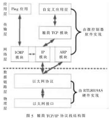
This module is responsible for the processing of the TCP/IP protocol. Since the Ethernet protocol only specifies the physical layer and the data link layer, it is necessary to implement the upper layer TCP/IP protocol in order to implement inter-process communication. However, this protocol is very complicated, and many functions are for PC platform applications, which are not used in embedded systems. In addition, the processing power and memory space of 8-bit microcontrollers enable complete TCP/ The IP protocol is simply impossible. Therefore, when using the software to implement the TCP/IP protocol on an 8-bit machine, the entire protocol stack must first be tailored according to the application requirements [4]. In this application, since only simple test data and test command transmission are required between the serial port and the Ethernet, a custom protocol is adopted at the application layer, and a TCP protocol capable of ensuring reliability is selected and performed at the transport layer. Targeted TCP protocol machine sanction, and only IP protocol that does not provide fragmentation and routing functions, ICMP protocol required to test network connectivity (only Ping response), and IP address to Ethernet are provided at the network layer. Address (MAC address) mapped ARP protocol. In this way, you get a streamlined TCP/IP stack that can be implemented and run on a low-end 8-bit machine. The complete structure of this protocol stack from the physical layer to the application layer is shown in Figure 5.
3.2.3 Application Module Design
Application modules provide services directly to user needs. In this design, according to the function division of the entire software module, the application needs to complete serial port communication processing and format conversion of serial frames and IP packets. Since the TCP/IP protocol stack transport layer of the embedded serial port-Ethernet bridge selects the TCP protocol (providing a streaming socket interface to the application layer) to ensure data transmission reliability, the application does not need to perform timeout retransmission. And the return confirmation processing only needs to complete the data transceiving operation of the serial port and the format conversion of the serial data frame and the IP packet. The use of shared data buffer and pointer technology for serial data frame and IP packet format conversion avoids data copying between protocol layers, which not only saves memory space, but also greatly improves the processing speed of packaging and unpacking; Since the amount of data to be transmitted by the serial port device is small each time, the data of the four serial port buffers adopts centralized packing and one-time transmission to reduce the number of network accesses, thereby improving communication efficiency and avoiding frequent The network congestion caused by short frame transmission; finally, the application module also provides the serial port attribute configuration function of the embedded serial port-Ethernet bridge. The user can pass the control port on the control computer according to the specific attributes of the serial port of each test device. Ethernet dynamically sets the data buffer and baud rate of each serial port of the bridge, which greatly improves the adaptability of the bridge.
Experiments show that the embedded serial port-Ethernet bridge proposed in this paper is applied to the vehicle speed sensor performance test platform, which not only can fully meet the communication requirements of the test platform, but also has the advantages of low cost, small size and high reliability. At the same time, on the hardware platform of this bridge, as long as the application module is slightly modified for specific application requirements, it can be applied to other automotive sensor performance test platforms (such as the wheel speed sensor performance test platform) as well as greenhouses, environmental protection, meteorology, etc. The occasion of monitoring. Therefore, the serial port-Ethernet bridge has strong adaptability and high promotion and application value.
China Modern Sconces,Modern Wall Lamp,Modern Wall Sconces,Modern Wall Lighting, we offered that you can trust. Welcome to do business with us.
the types of lamps include pendant lamps, table & floor lamps, chandelier, Wall Lamp ,desk lamp and etc., the materials include steel, metal, fabric, crystal, glass, aryclic and so on.
We offer samples with new designs every month to update our showroom and well display in lighting exihibtions.
We can make samples for his own designs as per shop drawings even potential idea from customers.
Modern Wall Lighting
Modern Sconces,Modern Wall Lamp,Modern Wall Sconces,Modern Wall Lighting
Monike lighting , https://www.monikelight.com