The ADS805 is an analog-to-digital converter with a moderate conversion speed, which is sufficient for most applications. Despite its relatively slow speed, it offers a well-balanced overall performance and is widely used in various fields such as CCD imaging, digital baseband processing, copiers, and testing equipment.
Key features of the ADS805 include:
- 20MHz bandwidth, 12-bit resolution, and high dynamic range
- High signal-to-noise ratio of 68dB
- Supports both internal and external reference voltage options
- Includes an input overshoot warning flag that can be used to adjust gain in signal conditioning circuits
- Uses digital error recognition technology to ensure excellent linearity
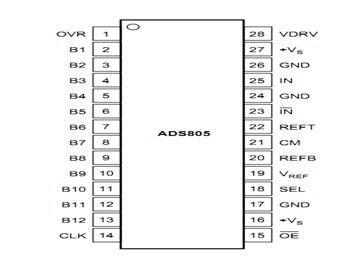
Pin 1 has a limit value indication function
Pin 15 is the output enable pin.
Pin 18 is used for selecting the input range.
Pin 19 is the reference voltage selection terminal.
Pins 20 and 22 are the bottom and top reference voltage inputs respectively.
Pin 23 provides supplementary input functionality.
Pin 28 is the input/output drive voltage.
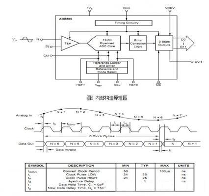
Figure 3: Timing diagram
As shown in the timing diagram, one data conversion cycle takes six clock cycles to complete.
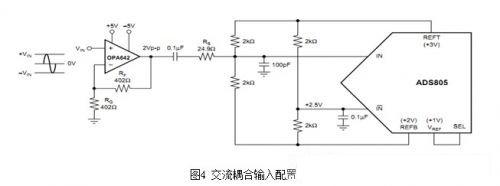
This signal represents an AC single-coupled cutoff configuration targeting the ADS804. It uses a low-distortion voltage feedback amplifier, the OPA642, and the top and bottom references (REFT, REFB) provide +3V and +2V reference voltages. Two resistor pairs (each 2kΩ) are used to create a common-mode voltage of approximately +2.5V, which biases the ADS805 effectively.

In applications where the signal bandwidth is critical, DC coupling is required to connect the signal directly to the ADC. This interface circuit helps adjust the DC level. The ADS805 typically operates at a common-mode voltage of +2.5V, determined by resistors R3 and R4, which then feed into the complementary input terminals R1 and R2. This setup ensures sufficient DC offset to reduce input noise effectively.
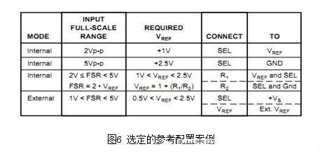
Reference Operating Conditions:
The ADS805 includes a bandgap reference circuit that can generate either a +1V or +2.5V reference output based on internal logic. Different reference voltages can be set using two external resistor configurations.
Auto Rotation Cleaver,High Precision Optical Fiber Cleaver,Optical Fiber Cleaving,Auto Fiber Cleaver
Guangdong Tumtec Communication Technology Co., Ltd , https://www.gdtumtec.com