0 Introduction The Ministry of Education put forward in the general idea of ​​college English teaching reform: reform the existing teaching mode, and change the mode of teachers, textbooks, chalk, blackboard and students, teachers and students to computer (network), teaching software, classroom synthesis. Personalized, active learning mode. The new "Teaching English Course Requirements (Trial)" also stipulates: Focusing on and emphasizing student-oriented, promoting individualized learning and independent learning. In order to adapt to the new teaching model, many colleges have set up independent learning centers or multimedia teaching centers. However, in the process of self-learning teaching practice, some problems have been discovered, such as students can not persevere, or for a variety of reasons, eventually halfway; self-learning is in the form, students play games, go online or do Other things in the process of self-learning Things; autonomous learning equipment failure rate is high, including student peripherals, monitors, headphones and other computer peripherals as well as tables and chairs. Analysis of the reasons, most colleges and universities only monitor the concept changes and rules and regulations, and the corresponding rules and regulations are not perfect or the implementation is not in place, the concept can not be completely changed, resulting in the independent learning process and teachers The teaching process lacks effective monitoring. Therefore, it is of great significance to study the equipment that monitors the learning process of college English autonomous learning to promote the smooth implementation and effective monitoring of college English teaching reform.
This article refers to the address: http://
1 The overall design of the autonomous learning monitoring system The monitoring of the English autonomous learning process is mainly to realize the audio and video monitoring of each independent learning classroom. The monitoring system studied in this subject can realize the monitoring of 32 independent learning classrooms, which can meet the needs of most colleges at this stage and the system expansion in the future. The overall scheme block diagram of this system is shown in Figure 1.
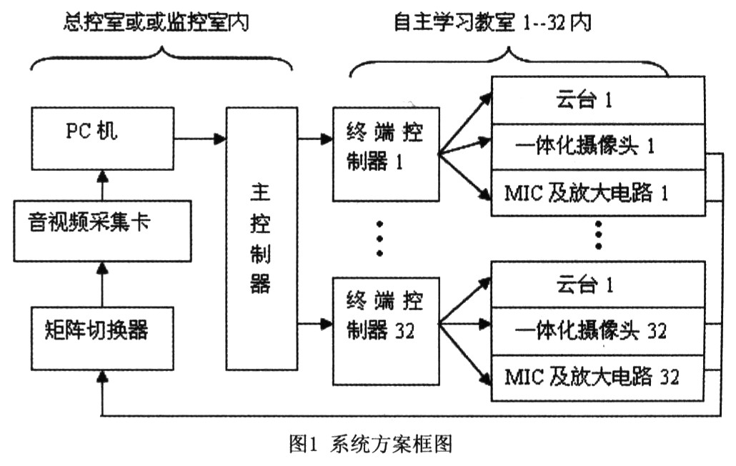
It can be seen from Fig. 1 that the video acquisition in the whole system is completed by the camera, the audio acquisition is realized by the MIC, and the amplification of the audio signal is realized by logarithmic amplification. Since the system can perform audio and video monitoring on 32 classrooms, considering the cost of the capture card and the effectiveness of the display (too many classrooms are also difficult to observe at the same time), the system uses a scheme of simultaneously monitoring 4 classrooms, 32 classrooms. Time-sharing monitoring, and for flexible monitoring, the system uses matrix switchers to switch and select audio and video. The selected audio and video signals are transmitted to the audio and video capture card and displayed and played on the PC. The system uses the Tianmin 10MOONSMD2040 capture card. At the same time, the selection of audio and video is controlled by the upper PC (control machine), that is, the control command is sent. The control commands are transmitted to the main controller of the system through the RS232 protocol, and the main controller receives the instructions, parses the instructions, and controls the corresponding peripherals to execute the instructions. The peripherals in the system are mainly matrix switchers and terminal controllers. The terminal controller mainly receives the control commands of the main controller to the pan/tilt and the aperture, and performs acquisition and amplification of the control commands and audio.
2 circuit design and implementation
2.1 main controller circuit and implementation Figure 2 main controller circuit schematic
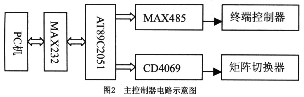
Because the main controller and the matrix switcher are installed in the same cabinet, the distance is very close, so it can be directly controlled by the I/O port of the MCU. To enhance the drive capability, add an inverter CD4069 to the output I/O port of the microcontroller.
2.2 Matrix Switcher Circuit and Implementation The design of this system is the monitoring of 32 channels of audio and video. To simplify the design, and the convenience of debugging, installation and upgrade, 32 channels of audio and video are not processed on one PCB, but It is divided into 4 sub-boards, each of which has N8 channel audio and video, and realizes 8 selection and 1 output functions of 8 channels of audio and video channels, that is, 4 sub-boards form a matrix switcher, and realize 32-select 4 output functions at the same time. The circuit diagram of each daughter board is shown in Figure 3.

In Fig. 3, J1...J8 are relay coils, and the double-pole double-throw relay J4078 realizes simultaneous switching of audio and video. J11 and J12 are jumper sockets. The jumper sets the address for the daughter board. When the set sub-board address is the same as the sub-board selection address (A0, A1, A2) of the main controller, the 4099 of the sub-board is in working state. At this time, through the channel selection command (cmd0, cmd1, cmd2) of the main controller, any relay in J1...J8 completes the switching action, and realizes simultaneous strobe of a certain channel of audio and video.
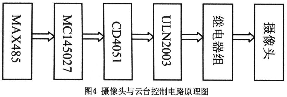
2.3 Terminal Controller Circuit and Implementation The terminal controller mainly implements two functions. First, it controls the integrated camera and pan/tilt according to the instructions of the main controller. First, it collects the voice signal of the current classroom and processes and uploads it.
2.3.1 Camera and PTZ control circuit and implementation As shown in Figure 4, the control command of RS485 control bus is received by MAX485 and the relay group action is controlled according to the command to realize the up, down, left and right rotation of the PTZ motor. Zoom, zoom/near, and light/dark adjustment of the aperture motor. The chip MC145027 is used to complete the decoding of the MCU instruction. The MCU sends the address command to the terminal controller. The control of the terminal controller sends the data command. Only when the address command sent by the MCU is the same as the address set by the MC145027, the MC145027 receives the data command of the MCU, that is, the control command. Thereby an addressable individual control for each terminal is achieved.
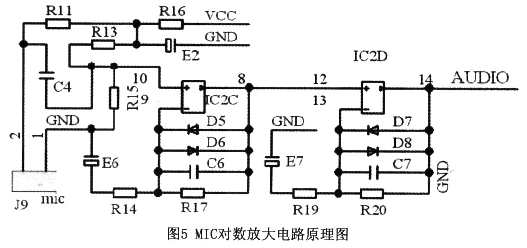
2.3.2 Voice Signal Acquisition and Processing Because it is necessary to collect voice signals from various locations in the classroom (generally in the range of 20 to 50 m2), it is obviously impossible to use ordinary microphone amplification circuits. The system adopts a logarithmic amplifying circuit for voice amplification, and relatively clearly collects voice signals at various positions within a range of 50 m2. The logarithmic amplification circuit designed is shown in Figure 5. IC2 is an operational amplifier, and the system uses LM358 to achieve two-stage operational amplification.
3 Summary Using sensor technology and electronic technology to achieve effective real-time monitoring of college English autonomous learning, the system design is simple, low cost, convenient and practical. It plays a very important role in improving students' self-awareness, monitoring the operation of independent learning equipment and software platforms, preventing unnecessary damage caused by human damage, and improving the stability and reliability of equipment operation.
Cables Utp Cat 6,Cat6 Patch Cables Bulk,Cat6 Patch Cord
Cambo Technology Co., Ltd. , http://www.gdeasycabling.com