1 System introduction
With the promotion of network multimedia applications, the embedded multimedia communication terminal system of independent models has become a hot research topic due to its low cost and good performance. The research of embedded video encoder with network communication function has become the core content in the design of multimedia communication terminal system. The working principle of the embedded network video encoder is to digitize the analog video signal and then send it to the network according to the international standard compression coding and network protocol processing. The client can receive the video data from the network and decode it in real time. The embedded video encoder is a high-performance processor and operating system that is tightly bundled, functionally specific, and designed to be independent. It is not affected by other software and hardware in the general computer system, and the performance is more stable and reliable. It is easy to implement the modular design of the system, which is easy to install, manage and maintain.
The TM1300 is a high-performance multimedia processor that uses the pSOS embedded real-time operating system and provides a full-featured online debugging tool. Designers can use the online debugging tools to develop TriMedia's various resources and debug various applications on the pSOS platform to ultimately implement the entire system. This paper presents a TM1300-based embedded video encoder for IP networks, and discusses the hardware and software design of the whole system in detail. We applied the encoder to the monitoring system to achieve real-time video transmission and achieved good image quality. The main functions of the network video encoder are: A/D conversion of video signals, H.263 video compression coding, H.323 network protocol processing, camera control and transparent data transmission.
2 hardware design
2. 1 Introduction to TM1300
The core TM1300 of the video encoder is a high-performance DSP from Philips that is designed for multimedia applications with high-quality video and audio processing. The powerful compiler and software development environment provided by TriMedia allows developers to write applications in C or C++ without using assembly language.
At the heart of the TM1300 is a 32-bit processor capable of 32-bit linear addressing with an addressability of 4GB. The TM1300 core processor uses a VLIW architecture that can execute five instructions simultaneously in each clock cycle. The TM1300 supports 16KB of high-speed data cache and 32KB of high-speed instruction cache, and high-speed data buffering is bidirectional. TM1300 also integrates PCI bus interface, which can be used as slave CPU in PC environment or embedded system as main CPU. TM1300 is different from general general purpose DSP, it has special video interface, audio interface and image protocol. Special units such as processor units and variable length decoder units. The image coprocessor is mainly used for image filtering or scaling to improve the processing speed; the variable length decoder can assist the kernel to complete Huffman decoding.
2. 2 overall hardware structure
The overall hardware structure of the network video encoder is shown in Figure 1. The encoder converts the analog video signal from the camera into the YUV format digital video signal via the AD conversion chip SAA7111A, and the TM1300 (1) compresses the image data stream into multiple rates according to the H.263 protocol, and then transmits it to the PCI data bus. The TM1300 (2), which is responsible for protocol processing, is encapsulated here and finally transmitted to the Ethernet interface unit RTL8139C(L) via the PCI bus to the Ethernet interface unit, which is sent to the IP network. The peripheral expansion module uses the W77E58 MCU as the core to control the camera and send and receive transparent data through two serial ports. CPLD mainly performs functions such as address decoding and PCI bus arbitration. The developed application is compiled and connected to the FLASH. After the encoder is powered on, the program in the FLASH is moved to the SDRAM through the bootloader in the EEPROM, and the system starts running. According to the above functions, the hardware design of the network video encoder can be divided into the following four functional units: (1) video coding unit; (2) protocol processing unit; (3) network interface unit; (4) peripheral extension unit.
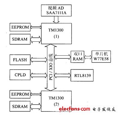
Figure 1 Network video encoder hardware overall structure
2. 3 video coding unit
The video coding unit is based on TM1300 (1). The peripheral components include EEPROM, 16M SDRAM, video AD chip SAA7111A, dual port RAM and 16MB FLASH. Among them, SAA7111A is Philips' enhanced video input processor (EVIP), input analog The video signals can be CVBS (PAL, NTSC, etc.) and S-Video (Y/C), and the A/D conversion outputs a YUV 4:2:2 digital video signal conforming to CCIR-656. The video input schematic is shown in Figure 2. The YUV digital video output port of the SAA7111A is connected to the video input port (VI) of the TM1300. The working mode of the SAA7111A is configured by the TM1300 via the I2C bus.

Figure 2 video input schematic
SDRAM is a synchronous dynamic RAM that provides Burst access for accessing applications, raw digital video data, and processed intermediate data. TM1300 (1) The external SDRAM uses 2 chips (12rank interface mode), each with a capacity of 4 &TImes; 1M &TImes; 16bit, with a total capacity of 16MB.
After a power-on reset, the TM1300 (1) reads the boot information from the EEPROM via the I2C bus, configures the clock divider register and the SDRAM register, then moves the bootloader in the EEPROM to the SDRAM starting from DRAM-BASE and begins. After executing the bootloader, the bootloader moves the corresponding application in FLASH to the SDRAM of TM1300 (1) and TM1300 (2), and each of them starts working normally.
2. 4 protocol processing unit
The protocol processing unit is based on TM1300 (2), which expands EEPROM and 16M SDRAM. Its memory and video coding unit have similar memory interface and startup circuit design. TM1300(2) operates in slave mode after power-on reset. The boot information is read from the serial EEPROM via the I2C bus, and the clock divider register and SDRAM register are configured. Then wait for the remaining work of the system startup by the TM1300 (1), including the MMIO space, the configuration of the DRAM space, etc., waiting for the TM1300(1) to move the corresponding application in the FLASH to the SDRAM of the TM1300 (2), TM1300 (2) ) You can start working properly.
2. 5 network interface unit
The schematic diagram of the network interface unit is shown in Figure 3. The RETL8139C(L) Ethernet controller of REALTEK is used as the core, and the Ethernet transformer ST6118T and RJ 45 sockets are connected to the local area network through twisted pair. The RTL8139C(L) interface is fully compatible with the PCI2.1 specification and can be easily hooked up to TriMedia's PCI bus. The Ethernet interface packs the video encoded and protocol processed data into Ethernet according to the Ethernet data format, and automatically monitors the data change at the receiving end, unpacks the received data, and transmits it to the TM1300 (2).

Figure 3 Schematic diagram of the network interface unit
Customized Solar Panel, 100watt solar panel,200watt solar panel, big solar panel, high efficiency high quality solar modules
different power customized and OEM logo customized solar panel
Customized solar panel data
solar cell type
mono crystalline half cut cell
power range
50watt to max 700watt
size and weight
different size and different weight if the power is different
solar panel type
monofacial or bifacial
solar panel color
sliver or black
Product details and pic


Customized Solar Panel,Noncrystalline Solar Panel Module,Cheap Price Pv Solar Module,Solar Photovoltaic Pv Panel
PLIER(Suzhou) Photovoltaic Technology Co., Ltd. , https://www.pliersolarpanel.com