1 Introduction In the information age, both mobile phones and home appliances are gradually integrated into the network. Information appliances integrate modern network communication technologies into traditional household appliances, making them accessible for information access, acquisition, storage, processing, and networking. Consumer electronics. The emergence of information appliances has changed the traditional way of controlling home appliances, not only to control them locally, but also to control home-connected home appliances through the Internet. Due to the popularity of mobile phones and PCs, the use of the existing Internet makes smart home possible.
This article refers to the address: http://
2 Intelligent home control system overall design The overall structure of the smart home system block diagram is shown in Figure 1. The system consists of two major parts: the PC-based home main monitoring center and dispersed in each monitoring point, with the microcontroller as the slave control The center's smart home appliances and monitoring equipment front-end system; using mobile phones as remote controllers, using the Internet as a bridge to achieve remote remote control.
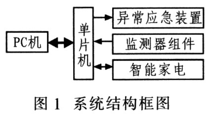
The system function realization is that the monitoring center PC collects various data in real time through the single-chip monitoring software. When an abnormal situation is found, the system sends information to the user through an alarm mode such as short message or image, and processes according to a preset emergency program, such as smoke, Gas detection is abnormal. The user can also remotely set the smart home appliance through the mobile phone or computer using an Internet browser to access the controller site, such as the air conditioner/electric water heater on/off and its temperature setting.
3 system hardware design The hardware system includes two parts: the remote control part mainly based on smart phones and the home control center mainly based on home PC.
3.1 Remote control terminal With the development of smart phones. Its function is rapidly enhanced. At the 2006 Science Fair, Nokia called its high-end mobile phone a "multimedia computer" and demonstrated its powerful features: video calling, mobile email, multiplayer online games, instant messaging, wireless payment and other value-added services, and stressed that mobile phones will Become the main tool for people to log on to the Internet to request information. Future smartphones will be more powerful, such as GPS, open source operating systems, TV authentication access, and home base stations. At present, 3G is accelerating the convergence between mobile networks and traditional Internet, so that mobile phones continue to develop toward PC.
Wireless Application Protocol (WAP) is an open global standard for communication between digital mobile phones, the Internet or personal digital assistants (PDAs) and computer applications. It can connect a large amount of information and multiple services of the Internet through WAP. People go to wireless terminals such as mobile phones and PDAs. This makes the mobile phone access to the user terminal PC become a reality, only need to install the corresponding software, and make corresponding access settings for the terminal PC. The user logs in to the smart home control center PC through the registered user name and password, obtains the managed terminal number (which can have multiple devices), and then selects a required control terminal to implement the user process and the smart home digital terminal hardware network card (MAC). Binding of the code). Thereby, the remote control of the smart home terminal is realized through the Internet by using the smart phone.
3.2 Hardware design of home terminal equipment Generally, the security equipment of smart home mainly refers to smoke fire alarm, gas detection, surveillance camera, power overcurrent/overvoltage detection, emergency call device and off/close device of monitored equipment, etc. Home appliances refers to embedded air conditioners, refrigerators, color TVs, electric water heaters and other home appliances. The PC is the main monitor, and the other monitoring modules are connected by the single-chip microcomputer to realize remote control. Take the fire equipment fire alarm alarm Sn-828-2PL (networked type) as an example (the technical parameters are shown in Table 1).

The functional features of the photoelectric wired smoke detector are: microprocessor control; automatic reset/power-off reset optional; infrared photoelectric sensor; networked output N. C. /N. O. Optional; LED indicating alarm; metal shield, anti-electromagnetic interference; strong environmental adaptability; SMT process manufacturing, strong stability; dust, insect and white light interference design. PIC16F873 type MCU has Harvard bus and RISC structure, 4 KB Flash program memory, 192 B on-chip data memory RAM, 14 kinds of interrupt sources, 8 levels of hardware stack, on-chip integrated synchronous serial port SSP (SPI and I2C) and synchronous and asynchronous Transceiver (USART) and watchdog circuits. In addition, the MCU has a 5-channel 10-bit precision A/D converter, which can meet the accuracy requirements of the system for analog signal conversion. The on-chip 128 B E2PROM can be used as a system power-down protection, eliminating the need for an external E2PROM power-down protection circuit, saving system resources. Therefore, this design uses PIC16F873 as the control core of various detectors and smart home appliances. Figure 2 shows the smoke monitoring module circuit.
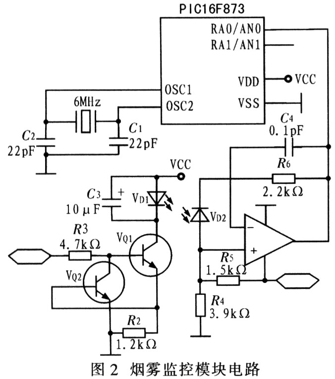
In Figure 2, in the interface circuit of the single-chip microcomputer and the fire detection alarm Sn-828-2PL, the photoelectric wired smoke detector connects the output signal to the RA0 pin of the PIC16F873, and the relative smoke signal is connected to the DC voltage/current signal. The RA0 pin of the PIC16F873 and the PIC16F873 complete the A/D conversion, and the corresponding program is processed inside the microcontroller to realize the monitoring.
4 Monitoring system program design The user terminal monitoring system program design can be divided into the management system design of the upper computer and the monitoring program design of the lower computer.
4.1 PC management program design The monitoring of smart home is realized by controlling the smart home digital terminal. The user logs in to the user terminal PC using the Internet, and the smart home control center PC transmits the user's instruction to the designated home terminal. Therefore, the design of the control center PC is equivalent to building a website for remote Internet access. The main design is to configure the computer's IP address, subnet mask, default gateway and DNS domain name. The computer is equivalent to a server. The management system design of the host computer can be written in languages ​​such as VB, which is mainly composed of several modules such as main control, setting, loop monitoring, alarm and communication (Fig. 3).
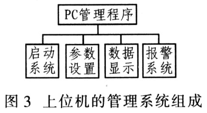
When the system is started, the main program starts from the main control module, and the startup of other modules is controlled by the main control module. This module mainly completes the initialization work when the system starts, coordinates the scheduling of other functional modules, and the system must start from the module to run normally. Parameter setting module: This module is a query setting window, which mainly sets various operating parameters of the system, such as adding, deleting, modifying and other basic function operations. The loop monitoring module: mainly displays the collected monitoring data in real time online and is responsible for writing it into the memory. The working process is to periodically read and collect the data information from the shared memory, and analyze the data and display it on the interface. Normal data and over-standard data can be displayed separately, making it easier for users to monitor data. Alarm and communication module: read alarm data from the alarm data shared memory, and send information or pictures to the user, remind the user to control and display the location of the alarm information and the cause of the alarm on the interface, so that the user can understand the alarm information; The communication module receives the monitoring data sent from each monitoring unit, and after processing, writes it to the monitoring data sharing memory for query.
4.2 lower computer monitoring program design The PIC16F873 type single-chip microcomputer is used as the slave controller. The system software design flow is shown in Figure 4. The hardware needs to adopt corresponding sensors, such as camera, smoke and other sensors to send the collected analog parameters to their respective signal processing circuits for processing (amplification, filtering, etc.), and then sent to the microcontroller PIC16F873 for A/D conversion, and then through the microcontroller Perform control processing. Because there are many sampling points, the monitoring modules are numbered, so that the PIC16F873 can collect the parameters of each monitoring module in a timed loop mode, and send the relevant parameter values ​​to the PC in real time, so that the user can access the PC through the smart phone. View the operation of each device. When judging the signal of the monitoring module i, if the judgment is normal, the loop monitoring module detects the parameter, and the next monitoring module is detected, so that the loop is reciprocating: when the detection signal of the module i is judged to be abnormal, an alarm is issued, and the corresponding alarm is started. The abnormal emergency processing program detects the next module signal at the same time, so that each monitoring module is sequentially detected in a loop.
5 Conclusion The system uses smart phones and PCs and some simple peripheral circuits to achieve wireless real-time monitoring of smart home working conditions. Its data acquisition system can be gradually extended to other states such as industrial control, instrumentation and other fields by improving sensor nodes. monitor. The biggest advantage of the system is that it can quickly build a network by using public mobile communication networks, the Internet and other resources, and has reliable communication and low investment, and has broad application prospects, but there are still areas to be improved and improved in various aspects.
These super bright LED Camping light and U-Tube Camping Light ,LED Tent Light is very easy to operate to make camping romantic and light.
We do with dry battery camping lantern and AC/DC rechargeable camping lantern ,LED Tent Light with good quality ,so that make camping night very nice.
Camp Lanterns, Outdoor Light Fittings, Work Lighting, LED Outdoor Light
Ning Bo LingSheng Electric Appliance co., Ltd , http://www.lsautotools.com