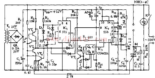
As shown in the figure, the electric fan integrated control circuit. The circuit is composed of a step-down rectifier circuit, a speed control circuit, a timing circuit, a gap switch circuit, and a thyristor control circuit. The buck rectifier circuit provides a DC voltage to the entire controller. The speed control circuit consists of IC1 (555) and BG1 ~ BG4. The oscillation period of the controllable multivibrator consisting of 555 and R3, R4, W1, C3, etc. is T=0.693 (R3+R4+Rw1) ) C3, adjusting W1 can only change the duty cycle of its oscillation pulse without affecting its oscillation frequency. For the logic drive circuit composed of BG3, D3, D4, when IC1 and IC2 both output high level, BG4 outputs a set of continuous zero-crossing pulses, triggering the thyristor SCR to turn on, so that the fan or other is controlled. The power to the circuit is turned on. Adjust W1 to control its duty cycle. It is possible to control the cycle ratio of the SCR output to adjust the output average voltage or adjust the output power. The average output voltage is: Vcp≈D·Vin=(R3+Rw1)/(R4+r3+Rw1)·220V. Adjusting W1 can make the output voltage AC (22~210)V, and the load power changes from 10% to 100%. The timing circuit consists of a multivibrator (IC2, R11, W2, C5) and IC3 (CD4024). The CD4024 is a 7-bit binary serial counter/divider, and the oscillation period of the oscillator is T=0.693 (R11+2Rw2)C5. The signal output from IC25 pin is added to IC3 for counting. When counting to 27=128 pulses (Q7 output), D terminal becomes high level, BG5 turns on, E point is low level, and IC1 and IC2 oscillate. Partially locked, the corresponding SCR is cut off, and the timing ends. The timing time td of the controller is from 1 minute to 10 hours and 40 minutes. The gap switch circuit is composed of the other half of IC2 and the single-stability circuit composed of R12 and C6. The output signal (9-pin) is connected with the output of IC1 through D4 to control the conduction of the SCR. The function. The controller can realize stepless timing and stepless speed regulation. When controlling the fan, electric heating, and motor products, it not only consumes reactive power, but also has long timing and high timing precision.
Lifepo4 Battery Pack,Lfp Power System For Agv,18650 Battery,Lithium Battery Pack For Agv
Henan Xintaihang Power Source Co.,Ltd , https://www.taihangbattery.com