Embedded Learning Notes UART Communication Protocol

The UART (Universal Asynchronous Receiver/Transmitter) is a crucial chip used for communication between a computer and serial devices. One important feature of the UART is that it provides an interface for data terminal equipment, allowing the computer to communicate with modems or other serial devices that use an RS-232C interface. As part of this communication process, the UART performs several key functions: 1. It converts parallel data from the computer into a serial data stream for transmission. 2. It also converts incoming serial data into parallel data that can be processed by the computer. 3. It adds a parity bit to the outgoing data stream and checks for parity in the received data. 4. It inserts start and stop bits in the transmitted data and removes them from the received data. 5. It handles interrupt signals from devices like keyboards and mice, which are also serial interfaces. 6. It manages synchronization between the computer and external serial devices. 
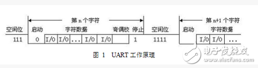
7. It supports asynchronous serial communication, where each character is sent one bit at a time, as shown below.

Embedded Learning Notes UART Communication Protocol

Each bit in the communication has a specific meaning: - **Start Bit**: A logic "0" signal that indicates the beginning of a character. - **Data Bits**: These follow the start bit and typically consist of 5 to 8 bits, forming a single character. The data is usually transmitted starting from the least significant bit. - **Parity Bit**: Added after the data bits to check for errors. It ensures that the number of "1" bits is either even (even parity) or odd (odd parity). - **Stop Bit**: A logic "1" that marks the end of a character. It can be 1, 1.5, or 2 bits long. - **Idle Bit**: Represents a high-level state when no data is being transmitted. **Baud Rate**: This refers to the speed of data transfer, measured in bits per second. For example, if a system transmits 120 characters per second and each character is 10 bits long, the baud rate would be 120 × 10 = 1200 bps. All these settings—data bits, parity, baud rate, and others—can be configured through the COM interface or directly in the code by setting the appropriate bits in the UART register. Understanding these configurations is essential for effective UART communication. Here’s a simple program that demonstrates how data is transmitted using the UART protocol:

Embedded Learning Notes UART Communication Protocol

In this example, the `uart_init` function is used to configure the UART settings. Let's look at how `uart_init` is defined in the system:

Embedded Learning Notes UART Communication Protocol

The development board provides three UART registers: UART0, UART1, and UART2. These registers are configured using various control registers such as `rUFCON`, `rUMCON`, `rULCON`, `rUCON`, and `rUBRDIV`. By setting these registers correctly, you can customize the behavior of the UART according to your application needs.

Elevator Advertising Projector

Elevator projector,projector Elevator,elevator projection,elevator projector advertising,Smart elevator projector,elevator advertising projector

Guangdong Elieken Electronic Technology Co.,Ltd. , https://www.elieken.com

Posted on