Engineers around the world are working hard to design hybrid and fuel cell vehicles, both of which require many embedded systems. What are the challenges these designers pose to designers, in which some systems rely on simple microcontrollers and communicate with other systems over the underlying network, but people are also introducing more complex micro- memories with larger memory. Controller. While many control algorithms and the subsystems they control are not new, it is a challenge to put all of these subsystems together in separate products and to ensure that they meet many of the most demanding requirements of the car.
This article refers to the address: http://
In this article, we will discuss the challenges inherent in the design of hybrid and fuel cell vehicle embedded systems. According to statistics, there are 500,000 fixed (static) fuel cell devices in the world in 2005. By 2010, there will be 2.5 million households using fuel cells, and there are 600,000 fuel cell vehicles in the world, accounting for the world's automobile production. 1%. In 2005, the total investment of companies engaged in fuel cell development exceeded $1 billion.
Fuel cell type system
The power system of a fuel cell vehicle is a major indicator that fuel cell vehicles are distinguished from other types of vehicles (internal combustion engine vehicles, battery electric vehicles, and oil-electric hybrid vehicles). The use of a fuel cell system as a power source is a hallmark of the fuel cell vehicle power system. Under normal circumstances, the fuel cell is not the only power source of the system. Due to the poor performance of the fuel cell in terms of peak power output capability and dynamic response of the power output, some auxiliary power source devices are often needed to be in power. It complements and improves the output capability to form a fuel cell hybrid system. The basic structure of the fuel cell for a vehicle is shown in Figure 3. This structure is similar to the series hybrid architecture except for the replacement of the fuel cell stack for the internal combustion engine.
Although fuel cell technology has been around for a long time, it is still a new technology in an uncontrolled environment where cars are located. Durability, reliability, and cost issues must be addressed before a large number of fuel cell vehicles are available. Moreover, the hybrid system of a fuel cell vehicle has various structural types, and the difference in the structure type often brings about a significant difference in the dynamics and economy of the entire vehicle. Therefore, various configurations of the fuel cell hybrid system are experimentally studied to obtain Reasonable and practical power system structure is a key part of the successful development of fuel cell vehicles.
The fuel cell itself is a complex system. It requires accurate control of the temperature and humidity of the fuel (hydrogen) and air entering the battery. For example, the air entering the fuel cell must be such that the temperature difference from the film in the battery pack is within 2 ° C and the relative humidity is in the range of 70-90%. If these requirements are not met, the battery pack will be damaged. Embedded systems that control fuel cell stacks must meet a variety of requirements.
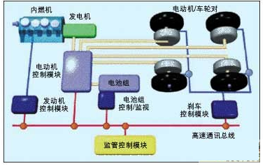
Figure 1: Series hybrid system
Hybrid system
As with the literal meaning, the hybrid propulsion system incorporates at least two different propulsion methods. In automotive applications, a typical hybrid system consists of an internal combustion engine (gasoline or diesel) and one or several battery-powered electric motors. One advantage of such a system is that the internal combustion engine can be designed as a device that always operates at maximum efficiency while the electric motor is used to provide basic or additional thrust during periods of high demand.
An internal combustion engine is a kind of power machine. It is a heat engine that converts the fuel into the inside of the machine and converts the heat released directly into power. The internal combustion engine in a broad sense includes not only the reciprocating piston engine, the rotary piston engine and the free piston type. The engine also includes a rotary impeller type gas turbine, a jet engine, etc., and an internal combustion engine is most commonly used as a reciprocating piston type. The piston type internal combustion engine mixes fuel and air and burns in its cylinder, and the released heat can generate high temperature and high pressure gas in the cylinder. The gas expansion pushes the piston to work, and then the mechanical work is output through the crank linkage mechanism or other mechanism to drive the driven mechanical work.
The architecture of a hybrid system is mainly composed of parallel and series, and the difference is reflected in the mechanical aspect. In a parallel hybrid system, the internal combustion engine provides mechanical power to the wheels in parallel with the motor that supplies the electrical power. In a series hybrid system, the internal combustion engine must first generate electricity and then convert it into power by the electric motor.
There are dozens of specific designs for each hybrid architecture. Figure 2 shows the electrical schematic of a parallel hybrid system. Figure 2 shows an electrical schematic of a series hybrid system. Both figures show the complete electrical system as well as the various embedded control systems.
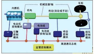
Figure 2: Parallel hybrid system
Figure 2 essentially shows the layout of the Honda Civic hybrid car that is currently on the market. In this layout, the purpose of the motor is to assist the internal combustion engine during acceleration (thus using a smaller and more efficient engine) and to slow down and brake. Recover energy and start the engine during the period.
The Civic hybrid engine reduces emissions and reduces fuel consumption in three ways. First, the energy that is normally wasted during deceleration and braking of the car is used to recharge the battery. Second, when the car is idle, energy is saved by turning off the internal combustion engine. The power of the motor is large enough to restart the engine and start driving the car synchronously. Finally, because the electric motor can help during high demand (such as rapid acceleration), a smaller engine is used in this car instead of the standard Civic engine.
The series hybrid system shown in Figure 1 uses an electric motor on each wheel. This series design can reduce emissions and reduce fuel consumption in the same way as parallel designs, but there are several other advantages. First, traction and energy recovery can be switched between the wheels, enabling fast traction control and anti-lock braking through the electric motor. This tandem architecture also provides the ability to drive all wheels without the need for expensive transmission boxes and differential gears. The second advantage of this architecture is the ability to naturally extend to any number of wheels, a advantage that is especially important for military applications. Finally, when the engine/generator is used to provide external power, decoupling the engine from the wheel may be more efficient.
As shown in the two figures, many embedded controllers are required to make a hybrid car work well. These controllers are interconnected and are typically interconnected using a high speed Controller Area Network (CAN) bus. The firmware in these controllers must control the respective parts of the system and coordinate in real time with other controllers. This requires the design and development of many new control algorithms and software, even for mature control systems such as engines, transmission and anti-lock braking systems (ABS).
Electronic challenge
There are no hybrid and fuel cell vehicles without the intelligence provided by embedded systems. These embedded systems currently have many components that are isolated from each other. Internal combustion engines (gasoline and diesel) and vehicle drives are currently controlled by embedded systems. Motor control and battery charging management have also matured in other industries. Fuel cells have also been used for space detection decades ago.
Many of the assumptions made in the design of existing electric vehicle systems are not suitable for hybrid architectures and fuel cell architectures. For example, many vehicle systems assume that the internal combustion engine must already be running before performing any tasks. If there is no energy when the engine is not running, is this correct? No. As long as the battery has sufficient power, the series hybrid system can operate with the engine off and the performance remains the same. The cost of the electronics (including hardware and software) portion may not be as much as 25% of the total cost of the final system, but the engineering effort required to develop algorithms and software for these components may exceed 75% of the total development cost.
There are many challenges that must be overcome to incorporate new electronic components into automobiles or other vehicles. The main challenges relate to cost, power consumption, operating environment, reliability and durability, safety and regulatory compliance. These well-known constraints exist in all embedded system projects, but they perform differently in hybrid and fuel cell vehicles. These challenges are discussed below and some suggestions are made on how to address them.
Cost and power consumption
Cars are cost-sensitive products, and their price pressure extends to the design of individual components. Because hybrid vehicles include traditional power supply systems and power systems (motors and batteries), consumers actually need to purchase two power supply systems. Although the cost savings from reduced fuel consumption can offset this high surcharge to some extent, the market will still require a lower initial cost.
Power management faces two major challenges. The challenges facing traditional cars remain unchanged: reducing the power consumption of each controller and draining excess heat. Because of the need to drive an external actuator, the driver circuit is a well-known high-power part, and to avoid damaging the electronics, the heat it generates must be dissipated. In addition, adding an electric motor to the vehicle means that more energy must be dissipated.
This new challenge stems from the design goal of the car - improving fuel efficiency. Embedded systems in vehicles must be very efficient and operate with very little energy. This is meaningless if the energy saved by shutting down the engine is then wasted while keeping the controller or actuator running (especially if the actuator is not needed).
To increase battery life, many battery-powered embedded devices use various algorithms to enter low power mode while in idle state. In hybrid or fuel cell vehicles, even this small amount of energy savings cannot be abandoned, especially when the total number of processors has been given. By entering a low power state while the software is waiting for a task, the embedded control system can contribute to improving the energy efficiency of the entire system.
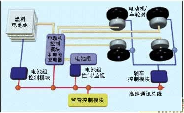
Figure 3: Fuel cell power supply system.
Operating environment
The electronic part of the control car must work in the harsh environment of high/low temperature and strong vibration. Suppliers of traditional automotive electronics are familiar with this environment. For example, the temperature range of underhood electronics (including microcontroller-based systems) is specified from -40 to 125 ° C. In many cases this temperature is incorrectly viewed as the ambient temperature within the enclosure, the actual electronic components Rated temperature. Tests performed under very harsh conditions have shown that the actual maximum temperature inside the enclosure is only 110 ° C, but this temperature is still sufficient to allow the water to boil.
Vibration is also a key condition. Vehicles powered by hybrids and fuel cells will bring suppliers of electric motors, batteries and fuel cells to the automotive industry for the first time. These new suppliers will have to design vibration indicators that meet the requirements of the aerospace industry in many cases.
safety
Many plaintiffs and lawyers are checking whether a flawed design has caused an accident and wants to be able to sue an engineer's employer for damages. The risks of such verification and legal proceedings forced auto engineers to spend many sleepless nights. To ensure that the design is safe under all conditions (even when a component fails), they must spend tens of thousands of engineering hours on Failure Mode/Consequence Analysis (FMEA) and Fault Tree Analysis (FTA).
Another safety feature is that the vehicle does not perform any action that the driver does not intend to make. With the advent of "by-wire" systems that separate drivers from devices, security has become a much more of a concern. Hybrid and fuel cell systems are inherently systems for line-driven, line-controlled braking and line-controlled driving. In many cases, this will require fault-tolerant system design and redundant design.
Reliability and durability
Automotive electronics need to operate reliably under a variety of conditions, typically 10 years/100,000 miles for trucks and 15 years/150,000 miles for trucks (these are typical values ​​and slightly different between different OEMs).
Some controllers are never actually turned off, they continue to run in a power-saving state, even when the car is out of service.
Design Tools
With modeling tools such as UML, Matlab/Simulink, and AscetSD, you can develop powerful products. It is particularly worth mentioning that this approach has one major advantage: it allows offline simulation of the system on the workstation. Through modeling, we can ensure that the system works properly under all conditions by performing reliability and safety analysis early in the project, without having to wait until the final product test to find defects.
In order to test on actual vehicles, many of the previously announced early concept car designs have used Matlab/Simulink and used automatic code generation on rapid prototyping systems. The main obstacle will be to convert this intellectual property into a productiON-ready code that meets all of the aforementioned challenges.
By relying on the system simulations previously done at the design level, when the various components are in place, we can test the functionality of the system in a variety of environments and multiple error conditions. When the software enters the final automotive product, we have completed extensive testing and development and can use the vehicle to validate the model rather than developing a control system. This does not mean that vehicle-level verification is not required, but doing so will reduce risk and improve the quality of the final system.
Because the simulation software will run many times directly in the modeling environment, simulation and modeling work well together. The biggest challenge here is to build a simulation model that does represent the simulated equipment and has a high enough simulation efficiency so that the simulation can be completed in a reasonable amount of time.
Of course, it is also necessary to see if all the challenges of hybrid or fuel cell vehicle design can be met in these products, so that users are happy to own and drive these products.
Control impedance PCB
Many customers asked us what information we need for impedence control PCB.Here,there are two types for PCB manufacturer,a is single impedance ,just one trace ,two holes .and b is differential impedance,it always go with 1 pair (two trace with same width and space). For single impedance,you just tell us the trace width one which layer and what value you require .For differential impedance,trace width/space,layers and value. Our experience engineers will calculate following your instruction with Polar software.We may change trace width/space or stackup ,but please do not worry, if any changes,we will send you to approve before proceeding. Generally,the tolerance is 10%,and more accurate is 8% .All impedance boards ,we will test here and report.
Impedance Control Board,Impedance Controlled PCB,Gold Fingers PCB,Impedance Control PCB
Storm Circuit Technology Ltd , http://www.stormpcb.com