The charger is a device designed to replenish the battery of an electric bicycle with electrical energy. It typically consists of several key components, including a rectification and filtering circuit, a high-voltage switch, voltage conversion stage, constant current and constant voltage control circuits, and a charging management system. The primary function of the rectification and filtering circuit is to convert the 220V AC from the power grid into approximately 300V DC. This DC voltage is then processed through a high-voltage switching circuit, which converts it into a lower DC voltage suitable for charging the battery. The charging process is controlled by the charging control circuit, ensuring safe and efficient power delivery.
The charger has two main connectors: one for connecting to the power supply (mains) and another for connecting to the battery. Additionally, there are two LED indicators that display the power status and the charging progress.
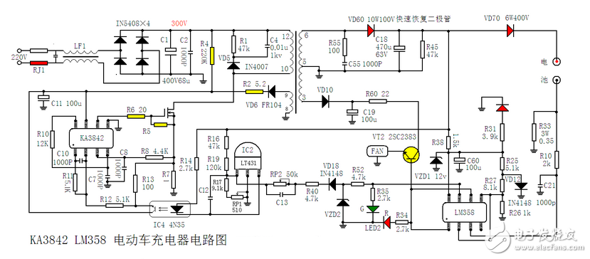
**Ka3842_lm358 Electric Car Charger Circuit**
PVC rigid tubes are commonly used for cable management and protection. They provide a secure and organized solution for routing and protecting cables in various applications, such as electrical wiring, telecommunications, and computer networking.
PVC rigid tubes are made from high-quality polyvinyl chloride (PVC) material, which offers excellent durability, flexibility, and resistance to impact, chemicals, and UV radiation. These tubes are available in different sizes and lengths to accommodate various cable sizes and installation requirements.
The rigid nature of PVC tubes ensures that cables are protected from bending, crushing, and other physical damages. They also provide insulation and shielding properties, preventing interference and maintaining signal integrity.
Installing PVC rigid tubes for cable management is relatively easy. They can be cut to desired lengths using a PVC cutter or saw, and fittings such as elbows, connectors, and couplings can be used to create bends and connections as needed. The tubes can be mounted on walls, ceilings, or floors using appropriate fasteners or adhesive.
Overall, PVC rigid tubes offer a cost-effective and efficient solution for organizing and protecting cables, ensuring a clean and professional installation.
Rigid Pvc Tubing,Pvc Split Sleeving,Pvc Cable Protection Sleeve,Pvc Protector Wire Sleeving
Dongguan Liansi Electronics Co.,Ltd , https://www.liansisleeve.com