The switching power supply uses high-speed switching and cut-off through the circuit control switch.
Converting DC power to high frequency AC power is supplied to the transformer for voltage transformation to produce one or more sets of voltages required! The reason for switching to high-frequency AC is that the efficiency of high-frequency AC in the transformer transformer circuit is much higher than that of 50HZ. So the switching transformer can be done very small, and it is not very hot when working! ! The cost is very low. If you do not turn 50HZ into a high frequency, then the switching power supply does not mean that the switching power supply workflow is:
The working process of the circuit:
a> After the switch S is turned on, the voltage across the transformer winding N1 is up and down, and the voltage across the N2 winding coupled with it is also up and down. Therefore, VD1 is in the on state, VD2 is in the off state, and the current of the inductor L is gradually increased. ;
b> After S is turned off, inductor L is freewheeled through VD2, VD1 is turned off. After S is turned off, the excitation current of the transformer flows back to the power supply through N3 winding and VD3, so the voltage that S is subjected to after being turned off is.
c> Core reset of the transformer: After the switch S is turned on, the excitation current of the transformer starts from zero and increases linearly with the increase of time until the S is turned off. In order to prevent the magnetizing inductance of the transformer from saturating, it is necessary to try to make the excitation current in S. After the shutdown, it will return to zero within the period of the next reopening. This process is called the core reset of the transformer.
The idealized waveform of the forward circuit: 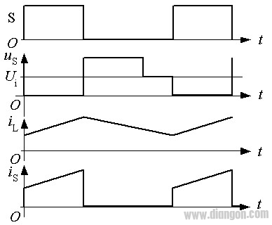
The core reset time of the transformer is:
Tist=N3*Ton/N1
Output voltage: When the output filter inductor current is continuous:
Uo/Ui=N2*Ton/N1*T
Core reset process: 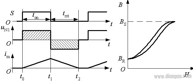
2, flyback circuit flyback circuit schematic 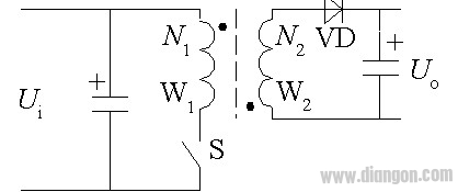
The transformer in the flyback circuit acts as an energy storage component and can be seen as a pair of mutually coupled inductors.
work process:
After S is turned on, VD is in a state of disconnection, the current of the N1 winding increases linearly, and the energy storage of the inductor increases;
After S is turned off, the current of the N1 winding is cut off, and the magnetic field energy in the transformer is released to the output through the N2 winding and VD. The voltage after the shutdown is: us=Ui+N1*Uo/N2
The working mode of the flyback circuit:
Current continuous mode: When S is turned on, the current in the N2 winding has not dropped to zero.
Output voltage relationship: Uo/Ui=N2*ton/N1*toff
Current interrupt mode: The current in the N2 winding has dropped to zero before S is turned on.
The output voltage is higher than the calculated value of the above formula and increases with the load decreasing. Under the limit of zero load, the flyback circuit should not work in the open state of the load.
Idealized waveform of flyback circuit 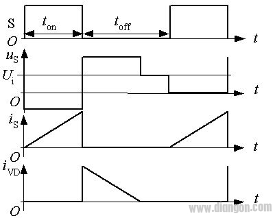
T Copper Tube Terminals,Non-Insulated Pin-Shaped Naked Terminal,Copper Cable Lugs Terminals,Insulated Fork Cable Spade Terminal
Taixing Longyi Terminals Co.,Ltd. , https://www.longyicopperterminals.com