EMI-compatible automotive switching regulators can be easily designed without the need to fully understand complex EMI. This paper shares the basic factors of successful implementation of switching regulators in an intuitive way without complex mathematical operations, including: slope control, filter design, component selection, configuration, noise spreading, and shielding.
The car itself is constantly changing, as is the electronics that drive the car. The most notable of these is plug-in electric vehicles (PEV), which replace the gas tank and internal combustion engine with a 300- to 400-V lithium-ion battery and a three-phase propulsion motor. Precision battery pack power monitoring, regenerative braking system and sophisticated transmission control optimize battery life so that the frequency of battery charging is reduced. In addition, today's electric vehicles or other types of vehicles have many electronic modules that enhance performance, safety, convenience and comfort. Many mid-range cars are equipped with advanced Global Positioning System (GPS), integrated DVD players and high-performance sound systems.
Accompanying these advanced devices is the need for higher processing speeds. As a result, today's cars incorporate high-performance microprocessors and DSPs that reduce the core voltage to 1V and increase the current by 5A. There are many challenges in generating such voltages and currents for automotive batteries between 6V and 40V, one of which is to meet the stringent standards of electromagnetic compatibility testing (EMC). Linear regulators used to be the primary method used to convert automotive battery voltages into regulated supply voltages, but they are now out of date. More precisely, the linear regulator reduces the output voltage and causes the load current to increase. Switching regulators are becoming more widely used, with concerns about electromagnetic interference (EMI) radio frequency and the importance of safety systems.
This article will explore the basic factors of successful implementation of switching regulators in an intuitive way without complex mathematical operations, including: slew rate control, filter design, component selection, configuration, noise spreading, and shielding.
Simple way to achieve switching power supply EMC
The purpose of this article is to try to design an EMI-compatible switching regulator without fully understanding the complex EMI. In fact, all of the problems associated with EMI come from the rate at which voltage and current variations within the switching regulator are not fully achieved, and how they interact with parasitic circuit components on the board signal line or within the component. For example, a 200 kHz step-down switching regulator powered by a car battery rated at 14 V and producing 5 V at 5 A. For considerable efficiency, the voltage slope of the switching node should only account for a small portion of the conduction time, for example 1/12 or less. The buck converter with continuous conduction mode (CCM) has an on-time of D/fsw, where D is the ratio of the duty cycle or pulse width modulation (PWM) signal turn-on time percentage to the entire time (ton and toff), and Fsw is the switching frequency of the converter.
For buck converters operating in CCM, the inductor current is always a non-zero positive current. In this case, the duty cycle is D = Vout / Vin, which in this case is 38% (5V / 14V). When using a switching frequency of 200 kHz, we quickly calculated the on-time to be 1.8 μs. To support this frequency, the rise/fall time of the control switch must be less than 90 nanoseconds. This makes us notice the first way to reduce noise, which is slope control. You may not understand it, but at this point we are very familiar with the harmonics associated with the PWM switching node, which is the control waveform of the switching regulator. If this waveform is represented by a trapezoid as shown in Fig. 1(a), the harmonics of the waveform can be expressed as shown in Fig. 1(b), which indicates the driving factor behind EMI. This Fourier envelope defines the harmonic amplitude that can be obtained by Fourier analysis or by calculating the on-time and rise time of the trapezoidal waveform.
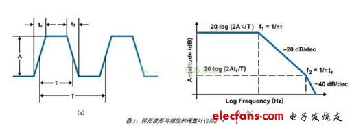
When observing the frequency domain, it can be seen that the trapezoidal waveforms with equal rise and fall times are composed of different harmonic signals, which are present in integer multiples of the fundamental frequency of the periodic signal. It is worth noting that the energy of each harmonic is reduced to 20dB/dec at the first turning point (on-time) of 1/(Ï€&TImes;Ï„) and subtracted from the second turning point of 1/(Ï€&TImes;tr). Up to 40dB/dec. Therefore, limiting the slope of the switching node waveform can have a significant impact on reducing the amount of emissions. Through this discussion, it should be clear that reducing the frequency of operation is also beneficial to reduce the amount of emissions.
AM RF band considerations
One of the difficulties in the automotive EMI specification is related to the AM frequency band. This band starts at 500kHz and lasts until 2MHz, which is very suitable for switching regulators. Since the highest energy component of the trapezoidal waveform is the basic component (assuming no board resonance), it can operate up and down the AM band.
Is the duty cycle important?
Another important factor is that if the load cycle is exactly 50%, all the energy of the complex trapezoidal switching waveform will be represented by odd harmonics (1, 3, 5, 7...). Therefore, operating at 50% duty cycle is the worst case. At the load cycle of 50% above and below, natural EMI diffusion occurs even if harmonics occur.
EMI and EMC standards
You can think of EMI as an unsuitable amount of energy that does not require too much and may violate the emission standards. In fact, EMI is a fairly low energy effect. For example, in the case of 1 MHz, as long as 20nW of EMI will violate the FCC's specifications for conducted emissions. Conducted emissions are measured by a spectrum analyzer that monitors the input source for high frequency components. The Line Impedance Stabilization Network (LISN) acts as a low-impedance filter for switching regulators and as a high-pass filter for spectrum analyzer line noise. Therefore, the input of the switching regulator is the next thing to note.
PRODUCT DESCRIPTION
- Just add water and essential oils
- Extremely quiet and easy to clean
- Cool mist / no heat involved / no risk of burns
- Automatically shuts off
- Runs 2 to 3 hours
- USB cord included
- Rotating LED Lights
- 1 Year Warranty
- Purify the air you breathe with this Usb Essential Oil Diffuser
- Convenient Usb Aroma Diffuser can be customized of your company name and logo
- Creates a lasting brand impression on a useful product for the home or office
- Essential oil help soothe the mind and improve mental well-being
DITUO Solutions Usb Oil Diffuser unites aromatherapy with modern scientific innovation to create a Usb Diffuser that plugs into your laptop with a USB cable. This mobile diffuser is PP material and diffuses essential oils for up to 3 hours. It utilizes high-frequency ultrasonic electrical vibrations to create an ultra-fine mist. This diffusion method doesn't utilize heat, which maintains essential oil integrity and holistic properties every time you use it.
USB Diffuser
Usb Diffuser,Usb Essential Oil Diffuser,Usb Oil Diffuser,Usb Aroma Diffuser
Shenzhen Dituo Electronic Co.,Ltd. , https://www.sz-dituo.com