When multiple digital tubes are used to display numbers, they are actually activated one at a time (only one tube is lit at any given moment). This technique leverages the visual persistence phenomenon of the human eye, also known as the afterglow effect. As a result, it appears as though all the digital tubes are lit simultaneously. This method is called dynamic display or dynamic scanning.
For example, if there are two digital tubes and we want to show the number "12," the high-order digit is first selected by turning on the corresponding transistor, and the segments are controlled to display "1." After a short delay, the lower-order digit is selected by activating the other transistor, and the segments are set to display "2." By repeating this process rapidly, the two digits appear to be on at the same time. Because the switching speed is fast enough, the human eye perceives both digits as being displayed together.
So, how long should each digital tube remain lit? In other words, what is the total time required to scan through all the digital tubes? The answer is that the entire scanning time should be within 10 milliseconds. When CRT (cathode ray tube) TVs were popular, the slogan "100Hz no flicker" was common. This meant that if the refresh rate exceeded 100Hz—i.e., the refresh time was less than 10ms—there would be no visible flicker. This serves as a hard benchmark for dynamic scanning.
You might wonder if there's a minimum limit. Theoretically, there isn't, but in practice, increasing the refresh rate beyond a certain point doesn't improve the visual experience. It only increases CPU load because more operations must be executed per second. Therefore, it's standard practice to design systems with a refresh interval around 10ms.
In our case, we have six digital tubes on the development board, so we will write a dynamic scanning program to verify the principle of dynamic display discussed earlier. Our goal is to implement a stopwatch function that can count up to 999,999 seconds. This requires handling both the timer functionality and the dynamic scanning of the display, making the program significantly more complex than previous examples.
When writing such a program, beginners are encouraged to use flowcharts to outline the entire process before starting to code. Setting up the structure of the program first and breaking down each part into smaller functions makes the implementation much smoother. This approach helps avoid confusion and ensures a clear path from concept to code. Figure 6-1 shows the flowchart for this example. Let’s walk through the steps in our minds according to the flowchart, then look at the actual code. You’ll see how the flowchart helps organize the logic and make the process more intuitive.
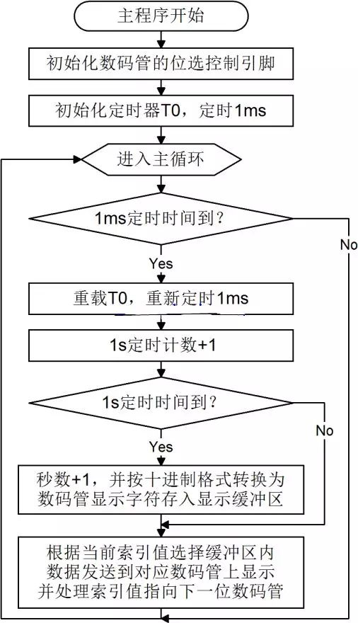
Figure 6-1: Digital Tube Dynamic Display Stopwatch Program Flow Chart
Here is the code:
```c
#include
sbit ADDR0 = P1^0;
sbit ADDR1 = P1^1;
sbit ADDR2 = P1^2;
sbit ADDR3 = P1^3;
sbit ENLED = P1^4;
unsigned char code LedChar[] = { // Digital tube display character conversion table
0xC0, 0xF9, 0xA4, 0xB0, 0x99, 0x92, 0x82, 0xF8,
0x80, 0x90, 0x88, 0x83, 0xC6, 0xA1, 0x86, 0x8E
};
unsigned char LedBuff[6] = { // Digital tube display buffer, initial value is 0xFF
0xFF, 0xFF, 0xFF, 0xFF, 0xFF, 0xFF
};
void main() {
unsigned char i = 0; // Dynamic scanning index
unsigned int cnt = 0; // Record the number of T0 interrupts
unsigned long sec = 0; // Number of seconds passed
ENLED = 0; // Enable U3, select control digital tube
ADDR3 = 1; // No need to re-initialize ADDR0-2
TMOD = 0x01; // Set T0 to mode 1
TH0 = 0xFC; // Initial value 0xFC67 for T0, timing 1ms
TL0 = 0x67;
TR0 = 1; // Start T0
while (1) {
if (TF0 == 1) { // Judge whether T0 overflows
TF0 = 0; // Clear T0 interrupt flag after overflow
TH0 = 0xFC; // Reassign initial value
TL0 = 0x67;
cnt++; // Count value starts from 1
if (cnt >= 1000) { // Check if T0 has overflowed 1000 times
cnt = 0; // Reset count after 1000 times
sec++; // Increment second counter
// Convert 'sec' into decimal digits and store in LedBuff
LedBuff[0] = LedChar[sec % 10];
LedBuff[1] = LedChar[sec / 10 % 10];
LedBuff[2] = LedChar[sec / 100 % 10];
LedBuff[3] = LedChar[sec / 1000 % 10];
LedBuff[4] = LedChar[sec / 10000 % 10];
LedBuff[5] = LedChar[sec / 100000 % 10];
}
// Complete digital tube dynamic scan refresh
switch (i) {
case 0:
ADDR2 = 0; ADDR1 = 0; ADDR0 = 0; i++; P0 = LedBuff[0]; break;
case 1:
ADDR2 = 0; ADDR1 = 0; ADDR0 = 1; i++; P0 = LedBuff[1]; break;
case 2:
ADDR2 = 0; ADDR1 = 1; ADDR0 = 0; i++; P0 = LedBuff[2]; break;
case 3:
ADDR2 = 0; ADDR1 = 1; ADDR0 = 1; i++; P0 = LedBuff[3]; break;
case 4:
ADDR2 = 1; ADDR1 = 0; ADDR0 = 0; i++; P0 = LedBuff[4]; break;
case 5:
ADDR2 = 1; ADDR1 = 0; ADDR0 = 1; i = 0; P0 = LedBuff[5]; break;
default:
break;
}
}
}
}
```
This program can be copied into Keil, combined with the flowchart, and downloaded to the development board to observe the results. The `switch` statement provides a cleaner and more structured way to handle the dynamic scanning of the digital tubes compared to using `if...else`. Each digit is refreshed every 1ms, resulting in a total refresh time of 6ms for all six digits. The human eye perceives them as being lit simultaneously.
In C language, the `/` operator corresponds to division, and `%` represents the remainder operation. For instance, to display the number 123456 on the digital tubes, you extract each digit by repeatedly dividing by 10 and taking the remainder. This allows each digit to be displayed correctly on the respective segment of the digital tube.
Using a `switch` statement for dynamic scanning not only improves code readability but also makes the logic easier to follow and maintain.
Phone Holder,Phone Holder For Mobile Phone,Car Air Vent Phone Holder,Mobile Phone Holder
Shenzhen ChengRong Technology Co.,Ltd. , https://www.laptopstandsupplier.com