When multiple digital tubes are used to display numbers, we actually activate them one at a time (only one tube is lit at any given moment). This technique leverages the visual persistence effect of the human eye, also known as the afterglow effect. As a result, it appears as though all the digital tubes are illuminated simultaneously. This method is referred to as dynamic display or dynamic scanning.
For instance, if there are two digital tubes and we want to show the number "12," we first enable the transistor for the higher-order digit, then set the segments to display "1." After a short delay, we turn on the lower-order digit by activating its transistor and set the segments to display "2." By repeating this process rapidly, the digits "1" and "2" appear continuously. Because the switching speed is fast, the human eye perceives both digits as being on at the same time.
So, how long should each digital tube be lit? In other words, what is the total time required to scan through all the digital tubes? The answer lies in the overall scanning time, which equals the lighting time of a single tube multiplied by the number of tubes. Typically, this time is kept within 10 milliseconds. In the era of CRT (cathode ray tube) TVs and monitors, a common slogan was "100Hz no flicker." This meant that if the refresh rate exceeded 100Hz—i.e., the refresh time was less than 10ms—there would be no visible flicker. This serves as a standard for dynamic scanning.
You might wonder if there's a minimum limit. In theory, there isn't, but in practice, increasing the refresh rate beyond a certain point doesn't improve visibility. It only increases the CPU load unnecessarily, as more operations must be executed per second. Therefore, in most cases, a value close to 10ms is chosen for the scanning interval.
On our development board, we have six digital tubes, so we will now write a program to implement dynamic scanning and verify the principle of dynamic display discussed earlier.
Our goal is to create a stopwatch function capable of counting up to 999,999 seconds. This makes the program significantly more complex than previous examples, as it must handle both the timing logic and the dynamic scanning of the digital tubes. For beginners, it’s recommended to use a flowchart to outline the entire process before writing the code. This helps clarify the structure of the program, refine each function, and implement it step by step, avoiding confusion during the coding process.
Figure 6-1 shows the flowchart for this example. Going through the steps in your mind according to the flowchart will help you understand the program better when you look at the actual code. This visualization makes the process smoother and easier to follow.
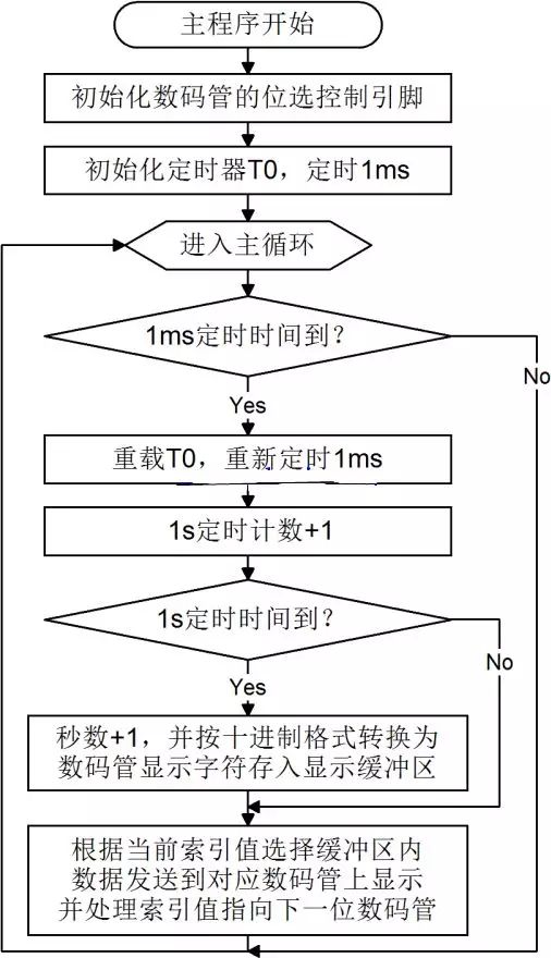
**Figure 6-1: Digital Tube Dynamic Display Stopwatch Program Flow Chart**
The following C code implements the dynamic scanning of the digital tubes:
```c
#include
sbit ADDR0 = P1^0;
sbit ADDR1 = P1^1;
sbit ADDR2 = P1^2;
sbit ADDR3 = P1^3;
sbit ENLED = P1^4;
unsigned char code LedChar[] = { // Digital tube character mapping table
0xC0, 0xF9, 0xA4, 0xB0, 0x99, 0x92, 0x82, 0xF8,
0x80, 0x90, 0x88, 0x83, 0xC6, 0xA1, 0x86, 0x8E
};
unsigned char LedBuff[6] = { // Digital tube display buffer, initialized to 0xFF
0xFF, 0xFF, 0xFF, 0xFF, 0xFF, 0xFF
};
void main() {
unsigned char i = 0; // Dynamic scan index
unsigned int cnt = 0; // Counter for T0 interrupts
unsigned long sec = 0; // Total seconds passed
ENLED = 0; // Enable U3, select digital tube
ADDR3 = 1; // No need to re-initialize ADDR0-2
TMOD = 0x01; // Set T0 to mode 1
TH0 = 0xFC; // Initial value for 1ms timing
TL0 = 0x67;
TR0 = 1; // Start T0
while (1) {
if (TF0 == 1) { // Check if T0 overflowed
TF0 = 0; // Clear T0 interrupt flag
TH0 = 0xFC; // Reload initial value
TL0 = 0x67;
cnt++; // Increment counter
if (cnt >= 1000) { // If 1000 T0 overflows
cnt = 0; // Reset counter
sec++; // Increment seconds
// Convert sec into individual digits and store in buffer
LedBuff[0] = LedChar[sec % 10];
LedBuff[1] = LedChar[sec / 10 % 10];
LedBuff[2] = LedChar[sec / 100 % 10];
LedBuff[3] = LedChar[sec / 1000 % 10];
LedBuff[4] = LedChar[sec / 10000 % 10];
LedBuff[5] = LedChar[sec / 100000 % 10];
}
// Dynamic scan refresh
switch (i) {
case 0:
ADDR2 = 0; ADDR1 = 0; ADDR0 = 0; i++; P0 = LedBuff[0]; break;
case 1:
ADDR2 = 0; ADDR1 = 0; ADDR0 = 1; i++; P0 = LedBuff[1]; break;
case 2:
ADDR2 = 0; ADDR1 = 1; ADDR0 = 0; i++; P0 = LedBuff[2]; break;
case 3:
ADDR2 = 0; ADDR1 = 1; ADDR0 = 1; i++; P0 = LedBuff[3]; break;
case 4:
ADDR2 = 1; ADDR1 = 0; ADDR0 = 0; i++; P0 = LedBuff[4]; break;
case 5:
ADDR2 = 1; ADDR1 = 0; ADDR0 = 1; i = 0; P0 = LedBuff[5]; break;
default:
break;
}
}
}
}
```
This program can be copied into Keil, combined with the flowchart, and downloaded to the experimental board to see the results. The `switch` statement provides a cleaner and more structured way to handle the dynamic scanning of the digital tubes compared to the `if...else` approach.
In C, the `/` operator performs division, and `%` calculates the remainder. For example, to display the number 123456 on the digital tubes, we extract each digit by repeatedly dividing and taking the remainder. This allows us to update each digit in sequence during the dynamic scanning process.
Using a `switch` statement instead of multiple `if...else` conditions improves readability and maintainability of the code. Both versions perform the same task, but the `switch` version is more elegant and organized.
Detachable Laptop Stand,Foldable Detachable Computer Stand,Detachable Ergonomic Laptop Stand,Detachable And Foldable Aluminum Laptop Stand
Shenzhen ChengRong Technology Co.,Ltd. , https://www.laptopstandsupplier.com