The ADS805 is an analog-to-digital converter that offers a balanced performance with a moderate conversion speed, making it suitable for a wide range of applications. It's widely used in CCD imaging systems, digital baseband processing, copiers, and testing equipment due to its reliable performance and flexibility.
Key features of the ADS805 include:
- 20MHz bandwidth, 12-bit resolution, and high dynamic range
- High signal-to-noise ratio (68dB) for clean signal acquisition
- Supports both internal and external reference voltage configurations
- Includes an input overshoot warning flag for gain adjustment in signal conditioning circuits
- Uses digital error recognition technology to ensure excellent linearity
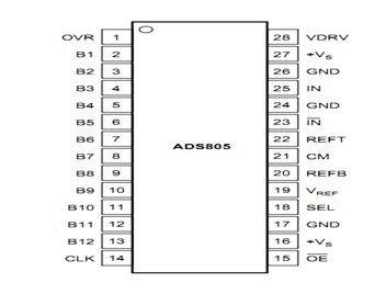
Pin 1 has a limit value indication function
Pin 15 is the output enable pin.
Pin 18 is used to select the input range.
Pin 19 is the reference voltage selection terminal.
Pins 20 and 22 are the bottom and top reference voltage inputs, respectively.
Pin 23 provides supplementary input functionality.
Pin 28 is the power supply pin for the input/output drive voltage.
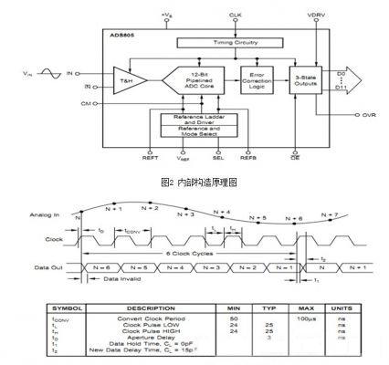
Figure 3: Timing Diagram
As shown in the timing diagram, one complete data conversion takes place over six clock cycles. This makes the ADC efficient and well-suited for real-time applications where timing precision is important.
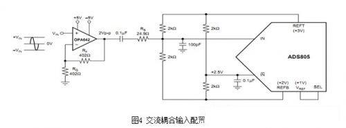
This signal is AC-coupled and designed for the ADS804. A low-distortion voltage feedback amplifier, the OPA642, is used to process the signal. The top and bottom references (REFT and REFB) provide +3V and +2V reference voltages, respectively. Two pairs of 2kΩ resistors create a common-mode voltage of approximately +2.5V, which helps bias the ADS805 properly.

In applications requiring a DC-coupled signal path, the interface circuit ensures proper DC level shifting. The ADS805 typically operates at a common-mode voltage of +2.5V, set by resistors R3 and R4. These resistors then feed into the complementary input terminals R1 and R2, providing enough DC offset to reduce noise and improve signal integrity.
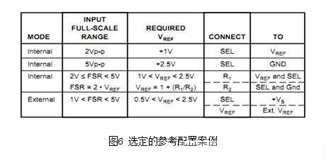
Reference Operating Conditions:
The ADS805 includes a bandgap reference circuit that can generate either +1V or +2.5V reference outputs. This allows for flexible configuration using two external resistor networks. The reference voltage can be adjusted based on the application requirements.
Fiber Optic Cleaver,Fujikura Fiber Optic Cleaver,Metal Precision Fiber Cleaver,Smart Automatic Fiber Cleaver
Guangdong Tumtec Communication Technology Co., Ltd , https://www.gdtumtec.com