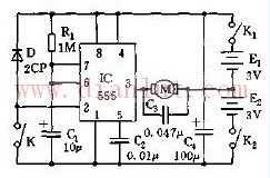
The control circuit of the toy electric car is shown in the figure. The time base circuit 555 and R1, Cl, etc. constitute a single stable time circuit. After the power switches SA1 and SA2 are turned on, Cl starts charging through R1. After about 1 second, the voltage on C1 is charged to 2/3 Vdd (4V), so that 555 is in the reset state, and the 3-pin output is low. The tube VT1 is turned on, the small motor M and the voltage source U1 form a closed loop to obtain electricity, and M enters a normal forward rotation, and the electric vehicle travels straight ahead. After the electric vehicle hits the obstacle during the travel, the elastic bumping contact lever (switch) SA closes due to the collision, and the charge on the Cl is quickly discharged, so that the 555 pin 2 is low, the 555 is set, and the 3 feet turn. It is high, VT1 is cut off, VT2 is turned on, so that voltage source U2, motor M and vT2 form a closed loop, M reverses, the car reverses or turns. The steering of the trolley is achieved by the reversing wheel during the reversing process. After the collision, the SA is automatically restored to the disconnected state due to the elasticity, and Cl is charged by R1, and its charging time is the monostable temporary stabilization time, and its size is td=1.1R1C1.
The graphical parameters are designed to be 1.1 seconds.
After 1.1 seconds, the voltage on Cl reaches the reset voltage required by 6 feet 2/3Vdd (about 4V), which causes 555 to return to reset state, 3 pin output low potential, motor M rotates positively, and electric vehicle moves forward. Travel straight.
Such sA in the traveling, collision, reversing and advancing circuits is an elastic touch switch for hitting the vehicle, which is normally disconnected; the small motor M is a toy motor, such as a 131 type machine; VTl and VT2 are PNP and NPN type triodes respectively. , should be paired when purchasing. The 8550 tube is of the Si-PNP type, and its power is Pcm=lW, Icm=-1.5A, BVceo=25V, BVceb=6V; 8050 type tube is Si-NPN type, its Pcm, Icm, BVceo, BVcbo and 8550 tubes Same, but the polarity (flow direction) is reversed. When selecting a pipe, a pipe with hfe ≥ 100 and equal should be selected to achieve symmetrical control of the motor M.
Small computer system interface (SCSI) is an independent processor standard for system level interfaces between computers and intelligent devices (hard disks, floppy drives, optical drives, printers, scanners, etc.). SCSI is an intelligent universal interface standard.
The last SCSI device in the SCSI chain uses a terminator, and the intermediate device does not need a terminator. Once the terminator is used by the intermediate device, the SCSI card cannot find the future SCSI device. If the last device does not use a terminator, SCSI will not work properly. Terminator is composed of resistors, located at the end of the SCSI bus, to reduce the mutual influence of the signal, maintain the constant voltage on the SCSI chain.
Most of the SCSI devices have built-in terminators and use a jumper to control on / off. The SCSI device is highly intelligent and can automatically control the terminator on / off. For example, if a hard disk is connected to a CD-ROM, the CD-ROM can work normally regardless of whether the terminator of the hard disk is on or off. However, when two hard disks are connected, the situation becomes more complicated. Before two Seagate hard disks are connected, one hard disk terminator must be off. Before a Seagate hard disk is connected to a quantum hard disk, a hard disk terminator can work normally regardless of whether it is on or off.
SCSI-90°DIP Section
ShenZhen Antenk Electronics Co,Ltd , https://www.atkconnectors.com