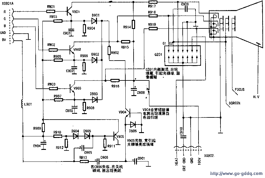
The final-stage view-and-release circuit plays an important role in the color television system. It amplifies the primary colors of R, G, and B to excite the picture tube and reproduce the color image. As illustrated in the diagram, transistors V901, V902, and V903, along with their respective bias circuits, serve as the amplifiers for the red, green, and blue primary colors. Transistor V904, diodes D904 to D906, capacitors C905 and C906, and resistors R909 to R912 collectively form the shutdown and brightening point circuit. In this circuit, V905 functions as the emitter dynamic bias element for the discharge tubes of the R, G, and B channels.
1. The primary color amplification circuit sends the R, G, and B primary color signals from pins 50, 51, and 52 of N201 to the base terminals of V901, V902, and V903 via RW01, RW02, and RW03. After amplification, these signals are sent to the CRT cathodes through resistors R917, R918, and R919, stimulating the CRT to restore the color TV image. Resistors R914, R915, and R916 provide collector power supply to transistors V901, V902, and V903, respectively.
2. When the shutdown and brightening point circuit operates normally, a 9V voltage is applied to the emitter and base terminals of V905 via R909, R910, R912, D904, and D905, turning it on. This makes V905 act as the emitter dynamic bias resistor for V901, V902, and V903. Simultaneously, the 9V voltage is connected to the positive terminal of C906 through R913, causing C906 to charge. The charging path is 9V → C906 positive → C906 negative → D906 → ground, resulting in a voltage of approximately 0.3V at the emitter of D906. At this time, V904 is cut off and has no effect on the view channel. Meanwhile, another path charges C905, with the charging circuit being 9V → C905 positive → C905 negative → R911 → ground.
At the moment of shutdown, the 9V voltage drops. Since the voltage across C905 cannot change abruptly, the voltage at the negative terminal of C905 decreases further to maintain the conduction of V905. Additionally, because the voltage across C906 cannot change abruptly, a voltage of about 9V appears at the negative terminal of C906, directly applied to the emitter of V904, cutting off D906 and saturating V904. The negative voltage turns on the ec pole of V904 and R902, activating D901, D902, and D903. Consequently, transistors V901, V902, and V903 are deeply saturated simultaneously, rapidly lowering the CRT cathode voltages and quickly discharging the CRT high voltage to achieve the purpose of shutting down the bright spot.
3. Additional circuit descriptions include the CRT filament (HEAT) voltage input from XS902 and the accelerating pole (SCREEN) and focus voltage (FOCUS) sent from the main board's upstream output transformer. These voltages are directly applied to the CRT header GZ01 and then sent to the CRT gun through GZ01.

In summary, this circuit design ensures efficient operation and precise control over the CRT’s performance, enabling the vivid reproduction of color images while also providing critical safety features during shutdowns or emergencies. Understanding these details is crucial for maintaining and troubleshooting color televisions effectively.
Silicone rubble cold shrinkable tube
Dongguan Zhonghe Electronics Co., Ltd. , https://www.zhonghesleeving.com