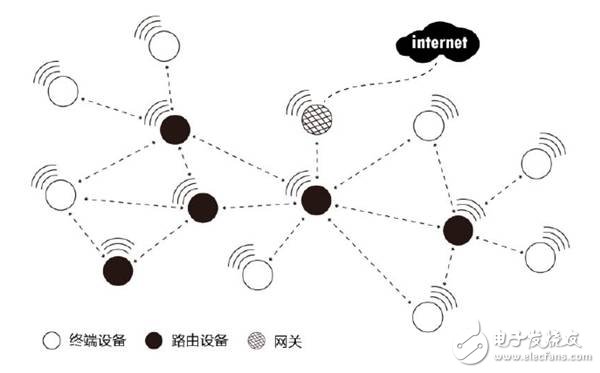
Wireless network technology is essentially a balance between power consumption, range, speed, and connectivity. So, can we have a system that is low-power, long-range, fast to connect, and easy to deploy? The Zigbee protocol standard includes a coordinator, a router, and end devices. Setting up a Zigbee network only requires a router or an end node in addition to the coordinator.
However, different application scenarios demand various networking structures—point-to-point, star, relay routing, hybrid, and more. Therefore, a networking protocol needs to be fast, efficient, stable, convenient, and flexible, which sets higher expectations for its design.
**First, the FastZigbee Protocol**
In other words, if any node on the network supports peer-to-peer data transmission without requiring a coordinator to manage the network, then any node can actively send data. This means users don’t need to worry about the underlying network structure, making it much easier to use.
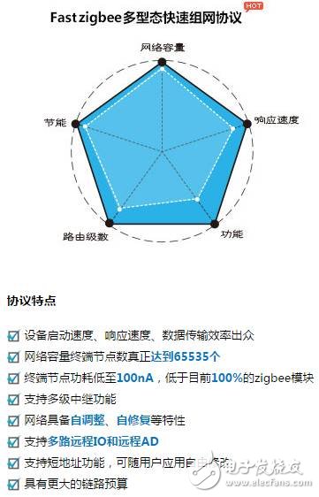
Based on this idea, ZLG Zhiyuan Electronics has developed the FastZigbee transparent peer-to-peer protocol based on the Zigbee protocol stack, after years of practical experience. Its key features include:
- Zero delay startup, no waiting for network access.
- Large node capacity, with a theoretical maximum of 65,535 nodes.
- 3-wire serial port full transparent transmission mode, allowing custom data formats.
- Dynamic configuration and self-organizing network capabilities, enabling quick deployment without additional development.
- Intelligent routing algorithms that allow rapid network expansion and recovery, making setup and maintenance easier.
**Second, Self-Organizing Network Implementation**
The FastZigbee protocol provides a solid foundation for networking. Can it also offer better support during deployment and construction? Absolutely. ZLG Zhiyuan Electronics has added self-organizing network functionality to the FastZigbee protocol, simplifying the complex development process of wireless products. Here's how it works using the AW516x series transparent transmission module as an example.
In self-organizing mode, the host module automatically selects an unused PANID and channel to form a separate network and assigns a unique local address to the slave module. Once the self-organizing function is enabled, the slave module can communicate immediately without any configuration.
**2.1 Hardware I/O Control**
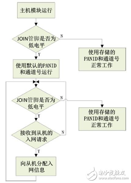
(1) The host module has two operational modes controlled by the JOIN pin (IO1) and the DETECT pin (IO2). When the JOIN pin is low, the host enters networking mode, allowing the slave module to join. When it goes high, the host moves into normal operation, and the slave module can no longer join the network.
If the DETECT pin detects a low level for more than 3 seconds, the host reacquires network parameters. It randomly generates a new PANID (0x0000–0xFFFF) and channel number (11–26), checks for conflicts, and regenerates if necessary. All slaves must then rejoin the network.
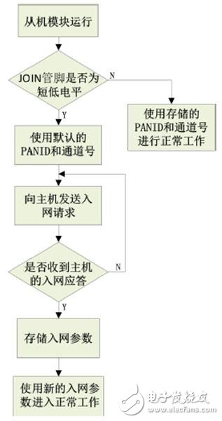
(2) The slave module has two working modes, determined by the state of the JOIN pin. A short low-level pulse (under 3 seconds) puts it in network application mode, while a long low-level (over 3 seconds) puts it in unwinding mode. If the JOIN pin is high, it uses stored PANID and channel numbers to enter normal operation.
**2.2 Software Instruction Configuration**
In addition to hardware control, the host module can also allow the slave to join via commands. For example, sending a specific command enables the host to accept network access requests from the slave for a set window period. After that, the host returns to normal operation.
Commands can also be used to query stored slave information, check the status of master and slave modules, and more.
**Third, Test Case**
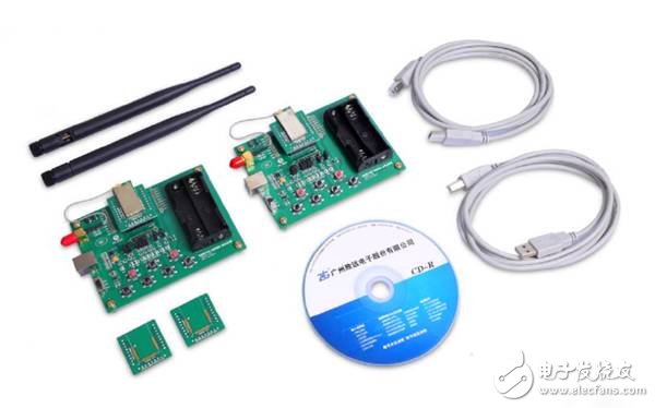
All operations are performed using ZLG’s Zigbee evaluation board, the AW516x Demo Board.
**Steps:**
1. Use Evaluation Board 1 as the host and Evaluation Board 2 as the slave.
2. Pull the JOIN pin (IO2) of Board 1 low to enable the slave to join.
3. Briefly pull the JOIN pin (IO2) of Board 2 low (under 3 seconds) to activate network mode.
4. Once connected, the slave returns to normal operation, and the host’s JOIN pin is pulled high to resume normal work.
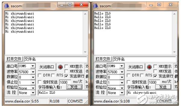
**Communication Test:**
Connect both boards to a PC and open two serial port debug tools for transparent data transmission.
Photocell Timer
24HR Electronic Timer socket with photocell.
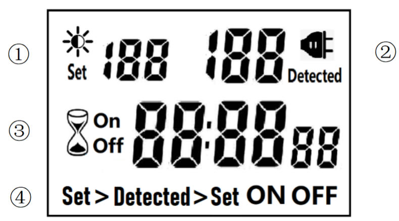
â‘ Light intensity setting
â‘¡ Light intensity detection
â‘¢ Countdown Timer ON & OFF
â‘£ 4 MODES:
Set > Detected: When the light intensity detection value is less than the set value, switch ON or OFF.
Detected > Set: When the light intensity detection value is greater than the set value, switch ON or OFF
ON : Always ON
OFF : Always OFF
NOTED:
1. The light intensity displayed by this machine is not the standard light intensity value (Lux), only the relative light intensity value.
2. The light intensity value is affected by the placement position and direction. Please determine the position first and then set it according to the actual light intensity detected. If you change the position or change the orientation, you need to reset the light intensity setting value suitable for the new position.
3. This product has built-in rechargeable battery. If it is not connected to AC for a long time, you need to connect the power supply to charge until the LCD can display normally.
MANUAL OPERATION
1. Press [UP" or [DOWN" to set the LUX value.
2. Press the [SET" key to start setting, and the P1 settable items will be flashed.
3. Press [UP" or [DOWN" to adjust the value.
4. Press [SET" key again to exit setting or enter next setting for countdown timer.
5. Repeat the [SET" key to start setting, and the P2 & P3 settable items will be flashed.


6. Press the [FUN" key to switch the working state in the following:
Set > Detected -> Detected > Set -> ON -> OFF
Set > Detected: Automatically switches when the detected ambient light intensity is darker than the set value
Detected >Set: Automatically switch when the detected ambient light intensity is brighter than the set value
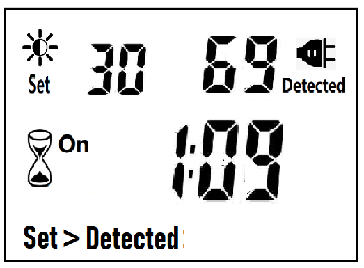
When the brightness meets the setting conditions, the countdown starts as below:
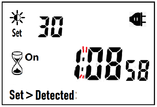
Note:when the countdown is ON, the detected value is not displayed.
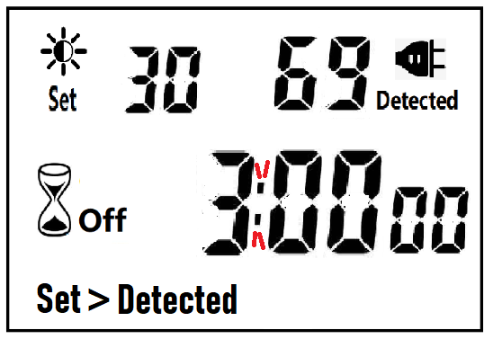
When the brightness does not meet the setting conditions, the countdown stops and waits:
After the countdown ON is reduced to 0, the countdown OFF starts immediately and the power is OFF.
After the countdown OFF is reduced to 0:
A. If the light intensity meets the set conditions, a new round of countdown will be started;
B. If the light intensity does not meet the set conditions, keep the power off and wait for the light to meet the conditions before turning on automatically.
NOTE:
1. If the power is cut off while the countdown is running, the countdown will be terminated immediately and the relay output will be off. After the power is turned on again, a new round of brightness detection will start.
2. Modifying the brightness value in the countdown operation will not affect the current countdown operation. After the off time of the current countdown, the new brightness setting value will take effect.
3. In the countdown on operation, change the setting value of the countdown on, this countdown will still be timed according to the original setting value; the new setting value will take effect when the next countdown on starts.
4. In the countdown off operation, change the setting value of countdown off, this countdown will still be timed according to the original setting value; the new setting value will take effect when the next countdown off is started.
NOTE: the brightness setting value, countdown ON or countdown OFF, any one of which is equal to 0, cannot be switched ON or OFF automatically.
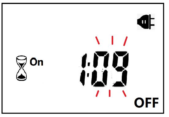
Manual Control
When ON or OFF is displayed, it means that the power supply remains ON or OFF, as shown in the figure below:

Power Detection and Standby Mode
With AC power supply, the icon  lights up and works normally.
When there is no AC power supply, the icon goes out, the brightness is not detected at this time, and the system enters the standby mode.
Photocell Timer, photocell timer socket, photocell sensor, photocell sensor socket, sensor plug, sensor switch socket, digital photocell timer, digital sensor timer
NINGBO COWELL ELECTRONICS & TECHNOLOGY CO., LTD , https://www.cowellsocket.com