Guide: Transformers are something everyone is familiar with, but have you ever wondered about the frequency of high-frequency transformers? Let’s dive into what a high-frequency transformer is and how it works.
1. Principle of High-Frequency Transformer – Introduction
A high-frequency transformer is one of the most critical components in a switching power supply. The turns ratio between each winding determines the output voltage. It operates at a frequency higher than that of an intermediate-frequency transformer and is primarily used as a switching power supply transformer in high-frequency systems. Depending on the application, the transmission power and operating frequency can vary significantly. A transformer designed for low-frequency operation will have different characteristics compared to one designed for high-frequency use, making the design approach unique for each case.
2. Principle of High-Frequency Transformer – Working Mechanism
The high-frequency transformer plays a crucial role in the switching power supply. Most switching power supplies use a half-bridge circuit, where two transistors are alternately turned on to generate a high-frequency pulse wave of around 100 kHz. This signal is then stepped down by the high-frequency transformer to produce a lower AC voltage. The voltage output depends on the turns ratio of the windings.
One common issue with high-frequency transformers is electromagnetic interference (EMI), which is caused by magnetic attraction between cores and repulsion between winding wires. These forces occur at the same frequency as the transformer's operation. Therefore, a 100kHz high-frequency transformer may naturally produce audible noise below 20kHz if not properly designed.
3. Principle of High-Frequency Transformer – Design Considerations
In the design of high-frequency transformers, minimizing leakage inductance and distributed capacitance is essential. Since these transformers handle high-frequency square waves, any leakage or capacitance can lead to voltage spikes, ringing, and increased losses. Typically, leakage inductance should be kept between 1% and 3% of the primary inductance.
Leakage inductance occurs when the magnetic flux between the primary and secondary windings isn’t fully coupled, especially between layers. Distributed capacitance arises between windings, between layers within the same winding, and between windings and shielding layers.
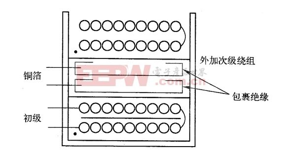
The primary winding should be placed on the innermost layer to minimize its length and reduce self-capacitance. For the secondary winding, adding 3–5 insulating layers between the primary and secondary helps reduce inter-winding capacitance and improves dielectric strength.
The bias winding is typically placed between the primary and secondary or on the outermost layer, depending on whether the power supply adjusts based on the primary or secondary voltage.
For further reading:
- High-frequency electronic transformer knowledge in switching power supplies
- Graphic winding method for high-frequency transformers
- High-frequency electronic transformers and their future development
Cell phone battery
industrial pc,pc fanless,small industrial pc
Guangdong ZhiPing Touch Technology Co., Ltd. , https://www.zhipingtouch.com