Guide: Transformers are a familiar component for most people, but have you ever wondered about the frequency of high-frequency transformers? Let's dive into what they are and how they work.
1. Principle of High-Frequency Transformer - Introduction
The high-frequency transformer is one of the most critical components in a switching power supply. The turns ratio between its windings determines the output voltage. Unlike traditional power transformers, high-frequency transformers operate at frequencies much higher than the intermediate range, making them ideal for use in high-frequency switching power supplies. Depending on their design, these transformers can either transmit large amounts of power at lower frequencies or smaller power at higher frequencies. This variation in performance requires different design approaches, which is essential to understand when working with such components.
2. Principle of High-Frequency Transformer - Working Principle
As the core of a switching power supply, the high-frequency transformer plays a key role in converting electrical energy efficiently. Most switching power supplies use a half-bridge circuit configuration, where two transistors are alternately turned on to generate a high-frequency pulse wave, typically around 100 kHz. This pulse is then stepped down by the transformer, producing a low-voltage AC output. The voltage transformation ratio is determined by the number of turns in each winding of the transformer.
One common issue with high-frequency transformers is electromagnetic interference (EMI), often caused by magnetic attraction between cores and repulsion between windings. These forces vary with the operating frequency, and even a 100 kHz transformer can produce audible noise if not properly designed. Understanding these factors is crucial for minimizing noise and improving performance in real-world applications.
3. Principle of High-Frequency Transformer - Design Principles
When designing a high-frequency transformer, it's important to minimize leakage inductance and distributed capacitance. These factors can cause signal distortion, voltage spikes, and increased losses during high-frequency signal transmission. Typically, leakage inductance should be kept between 1% and 3% of the primary inductance to ensure stable operation.
Leakage inductance occurs when the magnetic flux between the primary and secondary coils isn't fully coupled, especially between layers. Distributed capacitance, on the other hand, forms between windings, layers, and shielding, affecting the transformer’s overall performance.
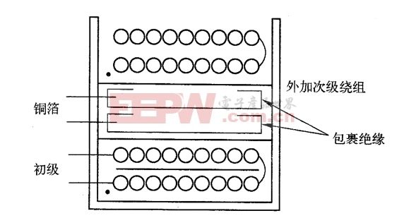
To reduce these effects, the primary winding is usually placed on the innermost layer to minimize its length and self-capacitance. The secondary winding is wrapped with several layers of insulation to reduce coupling capacitance and improve dielectric strength. A bias winding may also be added between or outside the primary and secondary windings to help regulate the power supply based on either the primary or secondary voltage.
Understanding these principles helps engineers design more efficient and reliable high-frequency transformers. Whether you're working on power electronics or exploring new technologies, knowing how these components function is essential for success in modern electronics.
Expand reading:
- High-frequency electronic transformer knowledge in switching power supply
- Graphic winding method of high frequency transformer
- High frequency electronic transformer and its development direction
cell phone battery
LV Series(23.8"-98")
IR touch frame,open frame monitor,multi touch infrared touch frame,ir touch frame 32 inch,55 inch ir touch frame
Guangdong ZhiPing Touch Technology Co., Ltd. , https://www.zhipingtouch.com