Yu Zhilou, Chen Naikuo, Niu Yufeng, Inspur Group
Keywords: Server Remote Management, IPMI, Baseboard Controller, Cross Platform
In recent years, with the rapid increase of network application services and the continuous improvement of business requirements, the load and number of servers have continuously increased, which has brought many challenges to the management of server systems.
1) To ensure that the server can provide network services safely and efficiently 24/7, it is necessary to be able to keep track of the operating status of the server at any time, to be able to detect or forecast failures in time, and to take prompt measures to resolve them.
2) The server system is often composed of many servers with different brands and different architectures. The interfaces and working platforms of different servers are different from each other, which makes it difficult to centralize and manage the servers.
Currently server system management mainly has the following methods:
1) Manual management means that the administrator checks and maintains the operation of the server in the equipment room. This management method consumes a lot of manpower and material resources, is inefficient, and cannot find and solve problems in a timely manner. It is difficult to cope with the increasing management. Difficulty and workload.
2) The use of remote monitoring software (such as SSH, Telnet), over-reliance on the operating system of the main server, and excessive use of system resources.
3) A special software tool developed for a certain type of server implements remote monitoring of remote servers on the console, and has problems such as poor scalability.
None of the above methods can cope with the ever-increasing management difficulty and workload in current server management. Their disadvantages are shown in Table 1.
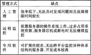
Table 1 Disadvantages of various server system management methods
1 Introduction to IPMI
In order to meet the needs of server management, in 1997 Intel, HP, Dell, NEC four companies began to develop a specification to solve the server can not monitor a different console on a single console, in 1998 initially proposed IPMI (Intelligent Platform Management The Interface Intelligent Platform Management Interface (API) specification provides system administrators with a standard interface for cross-platform management and monitoring of server operating status.
In 2001, IPMI was changed from version 1.0 to version 1.5. Based on the original specifications, LAN, serial ports, modems, and other communication interfaces were newly added, as well as PEF platform event filtering and configuration of alarm sending strategies.
The IPMI 2.0 version was introduced in 2004. New features such as encryption, authentication, VLAN, and SefM Over LAN (SOL) have been added. The IPMI 2.0 has been backward compatible with the 1.0 and 1.5 specifications, providing greater security, independence, and versatility. , And can achieve out-of-band management capabilities, the current specification has been more than 180 manufacturers support.
IPMI defines a standard message-based intelligent management platform and standardized records describing the management equipment of this platform. It has formed a hardware management specification that includes servers and other systems (such as storage devices, networks, and communication devices). Good portability and cross-platform features. In addition, since IPMI can operate under different system conditions, even when the server itself is down or powered down, IPMI monitoring of the server can still be performed normally.
Therefore, through the IPMI specification, it is possible to implement a server-based cross-platform server remote management platform with functions of configuration, monitoring, management, and alarm.
The IPMI system architecture is shown in Figure 1:
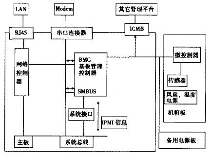
Figure 1 System architecture of IPMI
Baseboard Management Controller (BMC): It is the core of IPMI. It is a self-contained microprocessor independent of the server. It is responsible for the communication between the underlying components and the upper management software. The system management software manages each managed device. This is achieved through communication with the BMC. The BMC collects various sensor information and IPMI information such as SELs and FRUs through the IPMB bus, and can send it to the remote console through a serial port, a modem, and a LAN, and can also receive commands sent from the remote console. Then sent to the corresponding microcontroller through the IPMB bus, thus forming a server intelligent management platform that can realize remote monitoring independently of the server.
Watchdog timer: used to monitor the running status of the BIOS, various software, and application programs. When a timeout event occurs, the event is recorded in the system event log, and predefined actions such as restart and disconnection are automatically taken. Electricity, system interruptions, etc.
Sensors: Used to detect physical health information such as power supply voltage, chassis temperature, and fan speed.
PEF (Platform Event Filtering): Matches an event with an event filter table and decides whether to take appropriate actions for different events. These actions include power failure, power on, reset, and sending alarms. The order of priority is performed.
ICMB Bridge: Connects to the IPMB bus and communicates with another remote management platform through the ICMB bridge. In addition, other user boards can be added to extend the functions of the IPMI management platform.
The BMC actively looks at and collects information read by each sensor. When a predetermined threshold is found or an abnormal event occurs, the PEF determines whether to take corresponding measures through the platform event and records the event in the SEL and through the LAN, serial port, Modem and other methods send alarm information to the remote console. When remote control is required, the remote console sends a command to the BMC. The command uses the instructions specified in the IPMI specification. The BMC receives and records the event message in the system event log. , and send the command to the corresponding microcontroller or sensor. When the server is down or powered off, it can be remotely taken over by SOL to implement out-of-band management functions.
2 AST2050-based IPMI Controller
2.1 System Architecture
AST2050 integrates ARM9 processor and BMC management functions. The architecture of the server remote management platform based on AST2050 is shown in Figure 2:
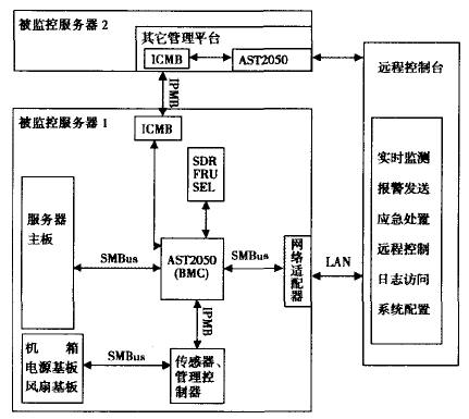
Figure 2 BMC system architecture based on AST2050
The remote console realizes the remote management of the server through the communication with the BMC substrate controller, sensors, and management controllers. The BMC is the core of the entire remote management platform and is a separate server independent power supply with separate microprocessors. , which is responsible for remote management platform communication with the underlying components (sensors, management controllers), using the AST2050 chip as the substrate controller, on the one hand it can collect the hardware information (such as voltage, temperature) read by each sensor, and the other A watchdog timer is also provided to monitor the operation of the BIOS, various software, and applications. The AST2050, sensors, and management controllers are connected to other host devices such as the main board, power board, and fan base through the SMBUS. The AST2050 uses the IPMB to acquire sensor information and send commands to the management controller. Messages used in communication between them are used by the AST2050. Is a standard IPMI information, so it can be easily added new components to extend the monitoring capabilities of the management platform, and can also communicate through the ICMB bridge and another management platform to achieve monitoring information sharing.
2.2 System Functions
2.2.1 Real-time detection
Real-time monitoring of various hardware information and their operating status, such as processor operating conditions, system temperature, fan speed, voltage, and whether various network application services are operating properly.
2.2.2 Alarm Sending
When the detected data exceeds a certain threshold (for example, the chassis temperature is too high) or an abnormal event occurs (the cooling fan stops working), it can be reported to the remote console and system administrators through the network in various forms.
2.2.3 Emergency Disposal
When a serious problem occurs in the system, the management platform can send instructions to the microcontroller embedded on each substrate to take some measures to ensure the safe operation of the server or data security through the AST2050.
2.2.4 Remote Control and Log Access
The event record (sensor recorded information, alarm information, event processing record) and hardware inventory are recorded and stored in the non-volatile storage area, so that the administrator can easily diagnose the fault according to log analysis, and the remote server is down or power is In the case of disconnection, the network administrator can continue to perform daily management such as startup, debugging, viewing, and software installation of the server through the out-of-band management function.
2.2.5 System Configuration
Through the console system administrator, you can set the threshold of each sensor, the destination of the alarm sending, and the platform event filtering table. You can add, delete, and modify the management authority.
2.3 System Working Principles and Workflows
AST2050 matches the collected system information with the platform event filter table. The platform event filter table records whether to take corresponding actions for different events. These actions include power failure, power cycle, interruption, reset, and alarm sending. , and can be performed in a certain order of priority. When a PEF-compliant event occurs, the AST2050 performs the corresponding operation and records the event in the system event log. The sensor data warehouse is used to save the data records read by the sensor. It is stored in the non-volatile database along with the SEL and FRU. In volatile storage areas, administrators can access them for troubleshooting and system maintenance when the server is down or powered off. When performing remote control, the remote console issues a command to the AST2050. After receiving the command, the AST2050 records the event message in the system event and sends the command to the corresponding management controller or sensor. When the server is down or powered off, remote management can be implemented to remotely control the server.
3 Conclusion
The separated processor collects the information such as the hardware and operating status of the monitored server, and can implement alarm and emergency handling functions. It can be operated independently within the system without depending on the status of the master server. This makes the server management system independent of the server itself. Even if the server is down or the power is off, the management and monitoring of the server can still be performed as usual.
The IPMI interface standard is adopted to make it have good versatility and extensibility. It can not only realize the centralized management of servers with different brands and different architectures, but also can load new functions on the basis of actual conditions. .
With the development of network technology, the application of servers has become more and more widespread. However, due to restrictions on working environment, business requirements and other conditions, it is increasingly difficult to manage servers, and it is difficult to ensure that servers can provide services in a long-term and stable manner. The emergence of the IPMI-based server remote management platform not only guarantees the normal operation of the server, but also reduces the maintenance and management costs of the server system, and will be more widely used in servers, telecommunications, industrial control, finance, etc. field.
Often used for both interior and exterior Illuminated Acrylic Signs, these illuminated Neon Signage include everything your business might need from logo, products, open time, home & festival decoration, lighting and advertisement.
Safe & low voltage, low power consumption, because the light source is LED, so even in the case of 12V, it can work normally.
Illuminated Signage,Illuminated Acrylic Signs,Outdoor Led Illuminated Signs,Illuminated Signage Letters
Shenzhen Oleda Technology Co.,Ltd , https://www.baiyangsign.com