Several good FET power amplifier circuit diagrams
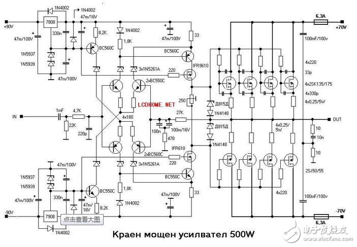
The field effect tube is multi-tube parallel output, 500W.
The biggest difference between the field tube and the general power is that the field tube is driven by voltage. There are some differences in the driving level. I haven't used a field tube amplifier. How does the sound quality depend on your design and process!
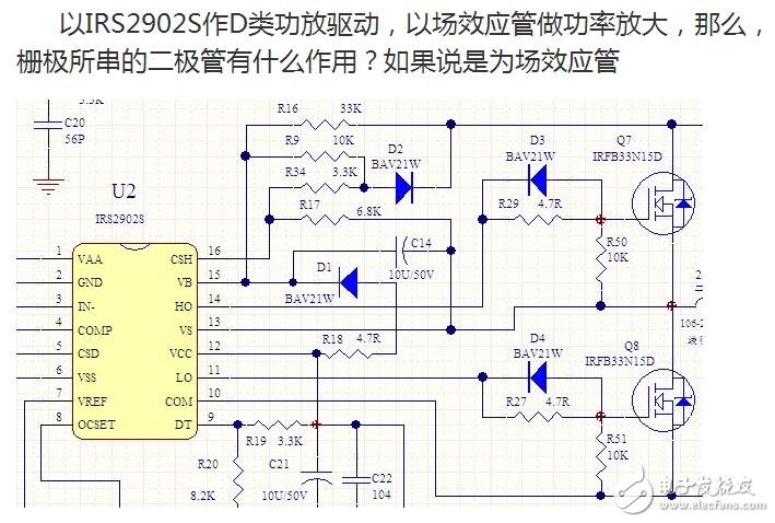
IRFB33N15D is a very good MOS tube, its conduction internal resistance is as low as 56mΩ, the maximum current is 33A, and the withstand voltage is 150V. It is often used in DC / DC converters. Of course, it is also often used in digital power amplifier .
There are also shortcomings. Its input capacitance is 2020pF. Like common MOS tubes, special circuits are used to drive it when driving it. Just like the parallel circuit of R29 and D3 in your circuit, it is also the industry ’s usual method. The role is:
When there is no R29, the gate of Q7 is directly connected to the front IC pin. The totem pole circuit is inside. Because it is a capacitive load, there will be oscillation, which will cause the driving waveform to ring. The resulting time is , The MOS tube is not opened enough, the internal resistance is large, and the efficiency is low. The series input R29 can eliminate this kind of oscillation, and the time constant of the input capacitance (Ciss) of the subsequent MOS tube is much smaller than the opening time of the MOS tube 13ns, and the time constant of 2020pF of 4.7Ω is 9.5nS, which meets the requirements.
When IRFB33N15D is driven with a standard circuit (equivalent to R29 is 3.6Ω), its recovery time is up to 130nS, which is also a common problem of MOS transistors. In order to speed up the shutdown (for this 9.5nS time), when shutting down, we hope that the gate level The resistance is 0, so the Schottky diode D3 (its operating frequency can be close to GHz) will be connected in parallel on R29 to accelerate the discharge.
The VGS of IRFB33N15D is between 3.0V and 5.5V. When actually driven, it depends on the operating voltage of IRS2902S, which is actually around 10V. The forward voltage drop of Schottky diode D3 is only about 1.2V (current 1A, but its ΔV / ΔI is about 0, and the dynamic internal resistance is extremely low), it has been ensured that Q7 and the gate are below VGS, which has no effect on shutdown. In addition, you have to learn the meaning of dynamic internal resistance. Like a power supply, its voltage drop may be 5V, but its internal resistance can be as low as a dozen milliohms.
The two field effect transistors in this circuit cannot be turned on at the same time, so when they are working, turn off first, and turn on slightly. The D3 and D4 diodes can quickly release the gate junction voltage of the field effect transistor when the driving voltage drops, so that the time for the tube to recover from the on state to the off state is greatly shortened. When the driving voltage rises, the gate junction capacitance of the tube is charged through R29 and R27, thereby delaying the on-time of the tube. In this way, the functions of turning off priority and turning on slightly are realized, which greatly avoids that one tube has not exited the conduction and the other tube has entered the conduction state.
The FirstPower CFPS(2V) and LFPS(6V/12V) series stationary batteries (OPzS battery) are the newly products which were developed at the end of 2005.
The performances meet the standard DIN40736 and IEC60896-21. tubularPositive plate can prevent the active material from falling off. The grid of positive plate is Pb-Sb multi-alloy
The design life is more than 20 years
Ensuring sufficient electrolyte for battery discharge
Industrial Opzs Battery,Industrial Stationary Opzs Battery,Industrial 2V Opzs Battery
Firstpower Tech. Co., Ltd. , https://www.firstpowersales.com