**What is the Main Electric Appliance?**
The main electric appliance is a crucial component in electrical control systems, responsible for closing and opening the control circuit to manage the starting, stopping, braking, and speed regulation of electric motors. It can act directly on the control circuit or indirectly through electromagnetic devices such as contactors or relays. These appliances are essential in electric drive systems, where they issue commands to regulate motor operations efficiently.
In control systems, the main electric appliance serves as an interface for human operators or automated signals, sending instructions to other components like contactors or relays. This allows precise control over the main circuit, ensuring safe and effective operation of machinery. Common examples include push buttons, limit switches, and universal switches, each playing a unique role in automation and control.
**The Role and Structure of the Main Electrical Appliance**
This article explores the functions and detailed structures of key components such as push buttons, position switches, and universal switches. These devices are fundamental in industrial and mechanical systems, enabling precise control over motor operations.
**1. Push Button Switch**
A push button switch is a manually operated control device that uses a spring to reset after being pressed. It is typically used to send signals to contactors or relays rather than directly controlling the main circuit due to its low current capacity (usually under 5A). The switch consists of a button cap, return spring, movable contacts, and a housing. When pressed, it first breaks one contact and then closes another, returning to its original position when released.
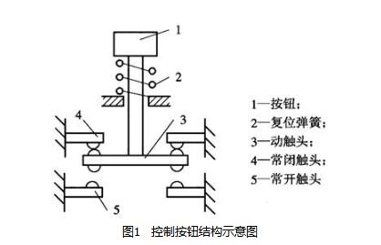
During operation, pressing the button causes the internal mechanism to move, changing the state of the contacts. This action is quick and reliable, making push buttons ideal for signaling in control circuits.
**2. Position Switch**
Position switches, including travel switches, micro switches, and proximity switches, are used to detect the position of moving parts and trigger actions accordingly. They are commonly found in machine tools, conveyor belts, and automated production lines.
**(a) Travel Switch**
A travel switch, also known as a limit switch, responds to the movement of a machine and controls its direction or stroke. It is often used in applications requiring precise positioning. There are two types: creep-type and momentary-type. Creep-type switches rely on the mechanical speed of the arm, while momentary-type switches use a spring-loaded mechanism to ensure rapid and consistent contact action.
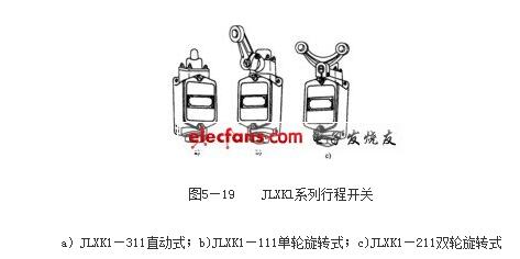
The LX19K model is a momentary-type switch that uses a stored energy mechanism to provide fast contact switching, improving reliability and reducing wear. Some models automatically reset, while others require manual intervention or reverse motion to return to their original position.
**(b) Role of Position Switches**
Position switches are vital for sequential control, position detection, and safety mechanisms in electrical systems. They help prevent overtravel, ensure proper alignment, and enhance system efficiency.
**3. Universal Switch**
A universal transfer switch is a multi-position, multi-circuit switch used for controlling various electrical functions, such as reversing motor direction or adjusting speed. It is commonly used in small motors and measurement instruments due to its flexibility and ability to handle multiple circuits simultaneously.
**(a) Structure and Working Principle**
The universal switch consists of a contact system, operating mechanism, rotating shaft, and handle. Its contacts are controlled by cams that change the circuit configuration based on the switch's position. This allows for complex control sequences with minimal wiring.
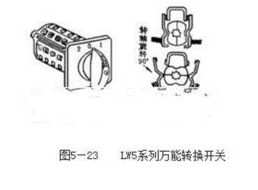
The symbol for a universal switch in circuit diagrams shows the contact positions and handle orientation. By rotating the handle, different sets of contacts are activated, enabling versatile control over electrical systems.
These main electric appliances form the backbone of modern control systems, providing reliable and efficient means of managing electrical operations in a wide range of applications.
The design of the terminal blocks with clamping yoke connections which has contact pressure and has with self-locking function.Providing test type,knife Disconnect,fuse type terminal blocks etc.The cross-sectional is 0.5-35mm².
Marker Carrier For Terminal,Screw Connection End Stopper,Terminal Block End Stopper,Terminal Connection End Clip
Wonke Electric CO.,Ltd. , https://www.wkdq-electric.com