One or three connection methods between the PLC and inverter are commonly used in industrial automation systems. These include switch quantity online, analog online, and communication online. Each method has its own advantages and considerations.
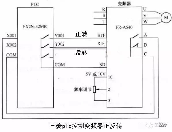
1. **Switch Quantity Online**
The inverter is controlled using the digital output of the PLC. This type of control is straightforward, with simple wiring and strong resistance to interference. The PLC’s switch output can directly connect to the inverter’s digital input, allowing for control of functions such as start/stop, forward/reverse, jogging, multi-speed operation, and time adjustment. However, this method only supports step-by-step speed regulation, which may not be suitable for applications requiring smooth speed changes.
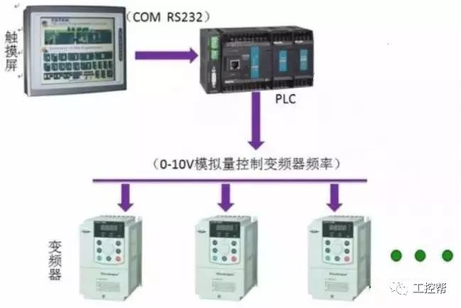
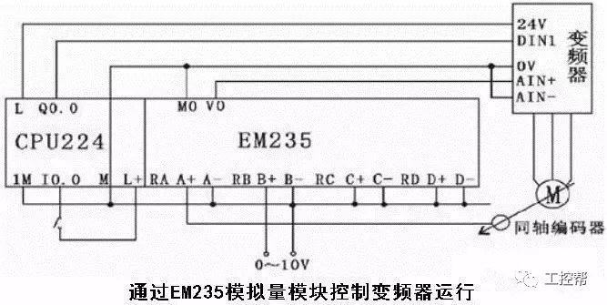
2. **Analog Online**
In this method, the inverter is controlled via an analog output module from the PLC. The PLC outputs a 0–10V voltage signal or a 4–20mA current signal, which serves as the analog input for the inverter to regulate its output frequency. This allows for continuous speed control, making it ideal for applications that require smooth and precise motor speed adjustments. However, the setup involves more complexity, including matching the PLC’s output impedance with the inverter’s input, and potential need for voltage dividers or resistors to ensure compatibility. Additionally, careful wiring is essential to avoid noise interference.
It is important to isolate the control and main circuits during installation to prevent electromagnetic interference (EMI) from affecting the system's stability. Shielded cables are recommended to reduce noise and improve reliability.
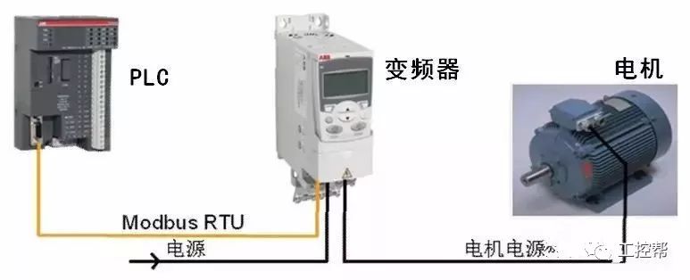
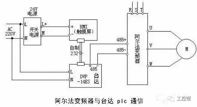
3. **Communication Online**
This method uses the RS-485 communication interface to connect the PLC and inverter. Most inverters come equipped with an RS-485 port, enabling multiple devices to be connected on a single bus. Up to 30 inverters can be connected, and each inverter can be addressed individually or through broadcast messages. A master station (PLC) controls all the slave units (inverters), allowing for centralized monitoring and control. This method significantly reduces wiring and offers flexibility in control configuration.
Advantages of serial communication include:
- Reduced wiring complexity
- Easy modification of control functions without rewiring
- Ability to set and adjust inverter parameters remotely
- Continuous monitoring and control of inverter performance
### Second Online Considerations
#### 1. Switching Signal Precautions
When connecting the inverter to the PLC, it is crucial to consider the type of switching signal being used. Some inverters use relay contacts, while others use transistor-based signals. Relay contacts may cause issues due to poor contact, leading to malfunctions. Transistor-based signals require attention to voltage and current ratings to ensure reliable operation.
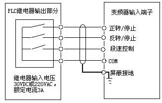
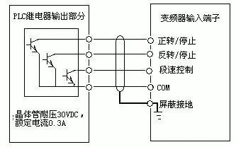
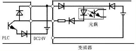
Proper wiring is essential to prevent damage from inrush currents, especially when using inductive loads like relays. Incorrect wiring can lead to component failure or operational issues. Examples of correct and incorrect wiring are shown below.
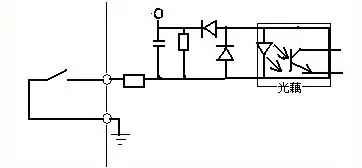
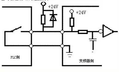
To avoid cross-talk between the external power supply and the inverter’s control circuit (typically DC 24V), it is recommended to use a diode to isolate the PLC power supply from the inverter’s input. This helps prevent electrical interference and ensures stable operation.
#### 2. Analog Signal Considerations
For analog signals, the PLC must match the inverter’s input impedance. Typically, signals are either 0–10V or 4–20mA. If the voltage ranges differ between the PLC and the inverter, additional components such as resistors or voltage dividers may be needed to ensure proper signal transmission without exceeding current or voltage limits.
Careful separation of control and main circuits is also necessary to minimize noise interference. Shielded cables and twisted pairs are recommended to enhance signal integrity and reduce EMI.
When using the PLC for sequential control, programming differences can introduce time delays. This should be taken into account in applications requiring high precision.
#### 3. Noise and Grounding Considerations
Since inverters generate significant electromagnetic interference (EMI), special attention must be given to grounding and shielding. Key recommendations include:
- Ground the PLC according to standard practices, avoiding shared ground lines with the inverter.
- Use noise filters, reactors, or other noise-reduction devices if the power supply is unstable.
- Keep inverter and PLC wiring separate within the same control cabinet.
- Use shielded and twisted-pair cables to reduce noise coupling.
By following these guidelines, you can ensure a stable, efficient, and reliable connection between the PLC and inverter, improving overall system performance and reducing downtime.
G1000 Oil Mud Pump,G500 Oil Mud Pump,G800 Oil Mud Pump,Oil Mud Pump For Oil Field
Jinan Guohua Green Power Equipment Co.,Ltd. , https://www.guohuagenerator.com