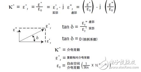
The dielectric constant, often denoted as K* or ε*r, is a measure of how a material interacts with an electric field. It represents the ratio of the complex dielectric constant (ε*) to the vacuum permittivity (ε0). The real part of this value, ε'r, reflects the ability of the material to store electrical energy when exposed to an external electric field. In most solid and liquid materials, ε'r is greater than 1.
The imaginary part of the complex permittivity, ε''r, is known as the loss factor. This component indicates the amount of energy lost or dissipated within the material due to the electric field. Unlike the real part, ε''r is always positive and typically much smaller in magnitude. It accounts for both dielectric losses and conduction losses within the material.
When visualized using a vector diagram, the real and imaginary components of the complex dielectric constant form a 90° phase difference. The angle δ between the real axis (ε'r) and the vector sum represents the phase shift. The tangent of this angle, tan δ, is commonly used as a measure of the material’s relative energy loss.
**How to Measure the Dielectric Constant**
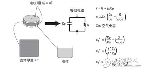
One common method for measuring the dielectric constant is the parallel plate technique. This method is widely used with impedance measurement instruments. The principle involves placing a sample material between two parallel electrodes, forming a capacitor. The capacitance is then measured, and the dielectric constant is calculated based on the result.
In practice, the test setup includes two electrodes placed in a fixture that holds the dielectric material. An impedance meter measures both the capacitance (C) and the dissipation factor (D), which are then used by software to calculate the dielectric constant and loss tangent.
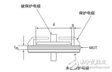
However, during testing, stray or edge capacitance can occur at the edges of the electrodes, leading to inaccurate measurements. These parasitic capacitances cause current to flow through both the dielectric material and the edge regions, introducing errors into the results.
To eliminate these errors, a guard electrode is often used. The guard electrode shields the edge area, preventing unwanted current flow and ensuring that only the capacitance from the dielectric material is measured. When combined with the main electrode, it forms a protected electrode system.
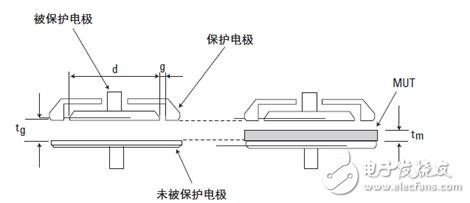
Another approach is the contact electrode method, where the electrode is directly in contact with the material under test (MUT). This method is simple and does not require special preparation of the material. However, it is prone to errors if air gaps between the electrode and the material are not accounted for.
Even with perfectly flat surfaces, an air gap is inevitable. This gap affects the measured capacitance, as it adds a series capacitance that distorts the result. To reduce this effect, a thin film electrode can be used, which minimizes the air gap and improves accuracy, though it requires additional preparation.
The non-contact electrode method offers a solution that avoids the issues of the contact method while still maintaining accuracy. It uses two capacitance measurements—one with and one without the MUT—allowing for the calculation of the dielectric constant. This method eliminates the need for thin film electrodes and reduces the impact of air gaps.
For accurate measurements, especially for solid materials like ceramics, specialized equipment such as a dielectric thermometer is used. The test fixtures are designed according to international standards, such as ASTM D150, and use a parallel plate electrode configuration. The upper and lower electrodes are precisely aligned, and a guard electrode helps minimize environmental interference.
Before testing, samples must be carefully prepared. The dimensions should be between 5–40 mm in diameter and less than 8 mm in thickness. The sample should be a flat disc with electrodes plated on both sides. The surface must be smooth and flat to ensure good contact with the electrodes, avoiding any measurement errors caused by air gaps.
Finally, a dielectric temperature spectrometer can automate high-temperature dielectric constant measurements. Its software provides detailed data across various parameters, including frequency, voltage, bias, temperature, and dielectric spectra. Results can be exported in multiple formats, making it a versatile tool for research and development.
Steel poles are commonly used to carry several types of electric power lines, distribution lines and lighting system. Distribution lines carry power from local substations to customers. They generally carry voltages from 4.6 to 33kV for distances up to 30 miles, and include transformers to step the voltage down from the primary voltage to the lower secondary voltage used by the customer. A service drop carries this lower voltage to the customer's premises.
Telecommunication Mast, Telecommunication Antenna Mast,Telescopic Telecommunication Mast,Signal Telecommunication Mast
Yixing Steel Pole International Trading Co., Ltd , https://www.yx-steelpole.com