The automotive industry has set off a technological revolution: electric vehicles (EVs) and hybrid vehicles (HEVs) are being put into production on a large scale and entering commercial operations. This means that cars with new structures are being introduced in large numbers. From an electronic system perspective, the technologies used to date for electric vehicles (EVs) and hybrid electric vehicles (HEVs) have come primarily from solutions that were originally developed for industrial applications over the past few decades. Since the automotive industry is commercially and technically different from the specific requirements of industrial systems, it is necessary to develop a dedicated solution.
This article refers to the address: http://
Given the drivetrain, especially the inverter, xEV manufacturers will have to deal with three major challenges: improving energy efficiency, reducing costs, and ultimately meeting functional safety requirements. The introduction of the ISO 26262 standard has driven the need for intelligent, cost-effective electronic solutions.
Inverter electronic structure
Figure 1 represents a typical structure of a traction inverter for use with a permanent magnet synchronous motor (PMSM). It consists of three main parts:
• Main logic circuit on the low voltage (LV) side
• Drive unit
• IGBT power module connected to a DC link.
The drive unit is usually made up of a single PCB that should be connected as close as possible to the power module to minimize the number of parasitic components in the IGBT gate signal path.
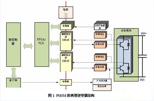
Each IGBT is driven by a gate driver whose main functions are:
• Provides electrical insulation between low voltage and high voltage. First-class solutions rely on inductive, capacitive or optical isolation.
• Drive the IGBT gate to maximize system efficiency. This means that the device should be able to supply enough current to quickly charge and discharge the gate. To achieve this, a rear drive unit (or boost unit) is often placed between the driver and the IGBT.
• Provides basic protection features such as undervoltage lockout (UVLO) or desaturation protection (DESAT).
In addition to these features, other requirements have been placed on the gate driver to meet safety standards. One of the main safety requirements stipulates that in the event of a fault, the system should prevent or limit the motor from generating excessive torque on the wheels so that the driver cannot control the vehicle. For non-synchronous motors, such strategies are (relatively) easy to deploy because the safety state of the system is achieved by turning on all switches; the IGBT is the device that is normally off, so the safe state is the default for the inverter status.
For permanent magnet synchronous motors (PMSM), the situation is more complicated because magnetic excitation can cause overvoltage at high rotational speeds (RPM). This can cause damage to the inverter components. For example, based on mechanical subsystems or chopper solutions, several methods have proven their feasibility in industrial systems, thereby limiting overvoltage conditions below the inverter rating. However, these support systems incur additional costs, resulting in a lack of practical availability of this solution for automotive inverters.
The deployment of anti-fault active short circuit (ASC) strategies can achieve system security goals. This strategy ensures that in each individual fault condition, the inverter can generate a zero vector (or active short circuit) by shorting the motor phase line.
The normal braking torque generated in this state does not cause the driver to control the vehicle.
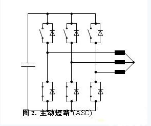
In order to be robust against failure, the structure supporting Active Short Circuit (ASC) relies on:
• A redundant power system (usually provided by a DC link) that ensures that certain critical functions of the engine board are always enabled to keep the IGBT open.
• Monitor the status of the IGBT to check in real time whether the PWM commands from the main logic circuit to the IGBT itself are consistent.
• Improve system testability during the application lifecycle to track potential system failures.
Separate implementation of such measures will not only significantly increase bill of materials costs, but will also increase the size of the drive board PCB, which can cause problems in meeting the space limitations of the interior of the car.
Digital drive: necessary measures
In order to optimize the inverter structure, two main schemes should be implemented:
• Functional integration: Each next-generation silicon technology increases the level of integration, meaning that discrete functions can be integrated within the ASSP. Related continuous integration measures can be found in many automotive systems, especially on traditional ECUs.
• Functional Overlay: The implementation of the ASC strategy relies on transmitting a series of signals beyond electrical isolation barriers. Since the gate driver has built-in galvanic isolation, it is ideal for superimposing multiple functions in an galvanically isolated communication channel.
For functional integration and functional overlay, the gate driver must be digitized, at least partially digital. This measure can be achieved by adding a digital interface to the gate driver. The communication link to the low voltage main logic circuit will be used to configure the device at system startup, provide status information for each drive during operation, and trigger intrusive system detection. It should be noted that the communication link does not necessarily directly control the switching behavior of the IGBT, but can be considered
Parallel channel for regular PWM commands. For this reason, standard medium speed communication interfaces, such as the Serial Peripheral Interface (SPI), would be a good choice.
Three levels of diagnostics can be integrated in the above manner:
• Gate Driver Level: Monitors the oscillator, power supply, internal data integrity, and more.
• Fault Injection Level: Injects hypothetical faults (such as virtual DESAT events) to verify that the system is able to react properly to such events.
• Signal Consistency Check Level: Reads the level of the signal sent and received by the gate driver through the SPI.
Figure 3 shows the optimized inverter structure.
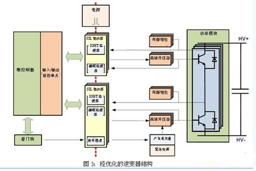
Some discrete security features have been distributed across different components of the system. An advanced IGBT status monitor and gate monitor are integrated into the drive. In this way, the IGBT state can be monitored in real time during the operation of the inverter. For example, IGBTs can be monitored by extending the familiar desaturation protection function.
Normally the DESAT protection function monitors the Vce voltage of the IGBT when it is turned on. When the voltage threshold is exceeded (usually 9V), the IGBT will automatically turn off when a short circuit condition is detected. The extended functionality of DESAT enables continuous monitoring of the Vce voltage. The result of the comparator is continuously sent to the low side and the information is provided to the low voltage logic in the form of a digital signal. Intelligent low voltage logic can be followed by
Compare the IGBT status to the original PWM command. Delay functions and filters are required to compensate for IGBT switching time and propagation time beyond electrical isolation barriers.
Advantages of integrating digital communication channels and gate monitors in the gate driver
The Mylar Speaker solutions come in a variety of shapes and sizes. We can provide various mounting configurations and performance alterations to fit any industrial application. Our Mylar speakers produce excellent sound output (dB) at specified frequency ranges. The unique characteristics of a Mylar cone allow us to keep tight tolerances during the manufacturing process. Additionally, Mylar is easily and consistently moldable, creating a cost-effective solution, time after time. It`s also beneficial in applications that are exposed to excessive moisture or humidity since Mylar has a high resistance to environmental factors.
Mylar Speaker
Mylar Speaker,Mylar Tweeter,Mylar Cone Speaker,Cellphone Mylar Speaker
Jiangsu Huawha Electronices Co.,Ltd , https://www.hnbuzzer.com