1 Introduction
The embedded system has brought people closer to the computer and formed a harmonious working and living environment. From a certain point of view, touch screen as an integrated input and output device in embedded computer systems, in manufacturing industry, process control, communications, instrumentation, instrumentation, automotive, marine, aerospace, aerospace, military equipment, consumer products, etc. They are widely used, affecting all fields of human work and life and have great application prospects. The programming of interactive functions with embedded systems is the key to the whole system design. Such a design process described herein gives a detailed explanation of the technical problems therein. The function design is based on the S3C2410 chip of the ARM920T core. The GX development board is used as the hardware platform, and the graphic interactive interface module implemented by Windows CE is the operating system.
2 system interaction function design
2.1 System Architecture
Often the architecture of an embedded system can be divided into four parts: processor, memory, input/output (I/O), and software. Since the application software and operating system of most embedded devices are closely combined, we do not distinguish them here, which is the biggest difference between embedded systems and general-purpose PC systems. The block diagram of the embedded design of the touch screen is shown in Figure 1.
2.2 Main functions of Windows CE
It is a newly developed modular graphical user interface multi-tasking operating system. It is a high-performance, high-efficiency real-time operating system that supports multiple CPUs and has good communication capabilities. OEMs can add any modules they need, or remove unwanted ones. Failure of one application in the system does not cause the entire system to fail.
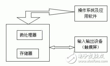
Figure 1 touch screen embedded design block diagram
2.3 Operating system support for touch screen
The operating system's support for the touch screen is based on the idea of ​​layering. The first is the application layer, the application written calls the touch screen/mouse event API (there are related API functions in the traction layer); secondly, there is a driver that supports the touch screen in the driver layer. The final device control is accomplished by calling the operating system kernel's touch screen device driver through a unified interface. The actual coordinate value of the touch screen is taken out, and the value is recorded in the initialization program. When the application needs to call the touch screen driver next time, the touch screen driver checks the initialization program, reads the correction value, and corrects the correction value. , after mapping, the relative coordinate values ​​are returned to the application.
2.4 touch screen circuit
GX development board is hardware platform, onboard SHARP 3.5〞TFT LCD screen LQ035Q7DB02, 320 & TImes; 240,262,144 colors, White LED backlight, with touch screen. SHARP LCD comes with four-wire resistive touch screen, can be directly driven with 2410 touch screen The circuit is connected, and the touch position is directly sampled by the ADC circuit built in the CPU.
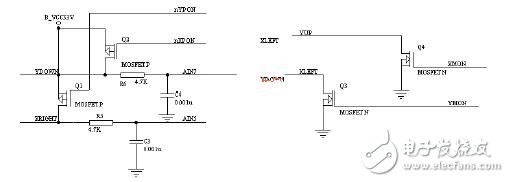
Figure 2 onboard touch screen circuit
2.5 touch screen control circuit
Touch screen control is done using the FM7843 chip. The FM7843 is a 4-wire resistive touch screen conversion interface chip. It has a 12-bit sampling analog-to-digital converter with a synchronous serial interface. The power consumption is 750μW at 125kHz throughput rate and 2.7V, while the power consumption in shutdown mode is only 0.5μW.
As a result, the ADS7843 is widely used in battery-powered small handheld devices due to its low power consumption and high speed. The FM7843 is available in a SSOP-16 lead package with a temperature range of -40 to 85 °C. In order to complete the electrode voltage switching and A/D conversion, the control word needs to be sent to the FM 7843 through the serial port. After the conversion is completed, the voltage conversion value is read through the serial port. A standard one conversion takes 24 clock cycles. Since the serial port supports bidirectional simultaneous transmission and can overlap between one reading and the next transmitted control word, the slew rate can be increased to 16 clock cycles each time. If the CPU can generate 15 CLKs (such as FPGAs and ASICs), the conversion rate can be increased to 15 clock cycles each time. The FM 7843 communicates with the ARM via the synchronous serial port. The data can be sent to the FM 7843 via the SendSIOData() function (uhal.c); the data is read from the FM 7843 via the ReadSIOData() function (uhal.c). The FM7843 can be turned on and off by setting the 6th position of the F port to 0 and 1. The data register of the F port is PDATF (44b.h). It is possible to determine whether there is a touch action by the external interrupt 5, and the query mode determines whether there is a touch action by the macro TCHSCR_IsPenNotDown() (tchscr.h).
3. Several key issues in the design
3.1 Custom Windows CE Platform
Windows CE is a multi-platform, scalable 32-bit embedded operating system. He is suitable for both embedded control modules for industrial equipment and for the development of consumer electronics. For different target device hardware environments, various modules are added on the basis of their cores to form a customized embedded operating system. It includes everything you need to customize your device, such as networking capabilities, real-time and small memory footprint, and multimedia and web browsing capabilities.
3.2 Windows CE` driver mode
The driver model of Windows CE` device has two forms: Stream Interface Driver and NaTIve Device Driver. From the implementation point of view, no matter which kind of driver can be used in single layer and layered mode. The code implemented in the multi-layer device driver is divided into two layers: MDD (Model Device Driver) and PDD (Platform Dependent Driver). The MDD layer provides a DDI (Device Driver Interface) function interface to the GWES module, which implements functions common to drivers of the same type of device, and the PDD implements code related to the specific hardware device of the platform. MDD accesses the hardware by calling a special PDD function.
3.3 Matching algorithm between touch screen and display
The X and Y values ​​returned by the FM 7843 controller are only A/D conversion values ​​for the voltage value of the current touch point, which is not of practical value. The value of this value is not only related to the resolution of the touch screen, but also related to the case where the touch screen is attached to the LCD. Moreover, the resolution of the LCD is generally different from the resolution of the touch screen, and the coordinates are also different. Therefore, if you want to obtain the position of the touch screen that reflects the LCD coordinates, you need to convert it in the program. The conversion formula is as follows:
x=(x-TchScr_Xmin)*LCDWIDTH/(TchScr_Xmax-TchScr_Xmin)
y=(y-TchScr_Ymin)*LCDHEIGHT/(TchScr_Ymax-TchScr_Ymin)
Where TchScr_Xmax, TchScr_Xmin, TchScr_Ymax and TchScr_Ymin are the range of the touch screen return voltage value x, y axis, LCDWIDTH, LCDHEIGHT is the width and height of the liquid crystal screen.
3.4 Operating system support for touch screen
The operating system's support for the touch screen is based on the idea of ​​layering. The first is the application layer, the application written calls the touch screen/mouse event API (there are related API functions in the traction layer); secondly, there is a driver that supports the touch screen in the driver layer. The final device control is accomplished by calling the operating system kernel's touch screen device driver through a unified interface. The actual coordinate value of the touch screen is taken out, and the value is recorded in the initialization program. When the application needs to call the touch screen driver next time, the touch screen driver checks the initialization program, reads the correction value, and corrects the correction value. , after mapping, the relative coordinate values ​​are returned to the application.
3.5 Confirmation of the coordinates of the touch screen
The coordinates acquired by the above method are relative to the coordinates of the touch screen, and need to be converted into LCD coordinates. Before this process, two coordinate calibration operations are required, and the averaging method is adopted here. First, two maximum values ​​and two minimum values ​​are obtained from the four apex angles of the touch screen, which are respectively counted as x_min, y_min and x_max, y_max. The X, Y directions are determined as shown in Table 1.
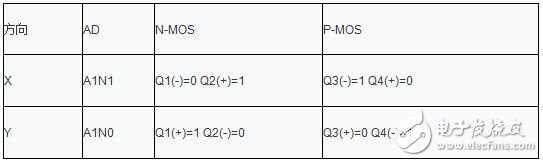
Table 1 Determination of X, Y direction
When the system is in the sleep state, Q1, Q3 and Q4 are in the off state and Q2 is on. When the touch screen is pressed, first turn on the MOS tube groups Q1 and Q4, X+ and X-loop plus +3.3V power supply, simultaneously turn off the MOS tube groups Q2 and Q3, disconnect Y+ and Y-, and then start the processor. The A/D conversion channel 1 (AIN1), the circuit resistance and the resistance output component voltage generated by the touch screen are pressed, and the voltage value is digitized by the A/D converter to calculate the coordinates of the X-axis. Then turn on the MOS tube group Q2 and Q3, Y+ and Y-loop plus +3.3V power supply, simultaneously turn off the MOS tube group Q1 and Q4, disconnect X+ and X-, and then start the A/D conversion channel of the processor. (AIN0), the circuit resistance and the resistance output component voltage generated by the touch screen are pressed, and the voltage value is digitized by the A/D converter to calculate the coordinates of the Y-axis. After the system reads the coordinate values, it closes Q1, Q3 and Q4, opens Q2, returns to the initial state, and waits for the next stroke.
After determining the X and Y directions, the coordinate values ​​are calculated as follows:
X=(x_max-Xa)&TImes;320/(x_max-x_min)
Y=(y_max-Ya)&TImes;240/(y_max-y_min)
In the formula:
Xa=(X1+X2+...+Xn)/n
Ya=(Y1+Y2+...+Yn)/n
Generally, the touch screen sends the voltage values ​​in the X and Y directions when touched to the A/D conversion interface, and the X and Y values ​​after the A/D conversion are only the A/D conversion values ​​of the voltage values ​​of the current touch points, and it is not Has practical value. The value of this value is related not only to the resolution of the touch screen, but also to the case where the touch screen is attached to the LCD. If you want to get the touch screen position that reflects the LCD coordinates, you need to convert it in the program.
4 Conclusion
More and more PDAs in embedded systems use touch screens as input and output devices. In this paper, the S3C2410 chip GX development board of ARM920T core is used as the hardware platform, and the embedded system touch screen interactive function module is designed. It has been applied many times in the products and works of the national college embedded system competition. The paper analyzes and discusses the key technical issues in the design. The software design flow chart and source code and other auxiliary programs are limited to the space.
MC Flex Outdoor Rental LED Display
Advantage of Outdoor Rental LED Display P3.91 P4.81 P5.95
1, Outdoor high resolution and high
brightness, smallest pixel in the world
3.91mm, unequalled image quality in outdoor environment.
2, Ingress protection reaches to IP65, weather
proof and dust proof.
3, High brightness uniformity and color
uniformity (≥95%)
4, Super thin and light with die-casting
aluminum cabinet design.
5, Good performance: anti-UV and anti-oxidation.
6,Large viewing distance: 140° in horizontal,
140° in vertical.
7, Excellent flatness and no splicing gap
between modules
8, Quick installation and removal with facile
connection lock
Outdoor Rental LED Display
Outdoor Rental LED Display,Outdoor Full Color Rental LED Display,Outdoor Rental LED Screen Display,Outdoor Curtain LED Display
Shenzhen Macion Optoelectronics Technology Co.,Ltd. , https://www.macion-led.com