introduction
At present, except for the departure station and the terminal station, many stations in the middle cannot guarantee the punctuality of the bus; relying on the driver to press the button to report the station, it is inevitable that errors will occur and mislead the passenger; the waiting person does not know the running status of the waiting bus. To this end, this paper developed a bus operation monitoring system based on GPRS and ZigBee, in order to better solve these problems.
In this system, the GPRS technology used in long-distance wireless communication and the ZigBee technology used in short-distance wireless communication complement each other. While expanding the monitoring range, it also improves the intelligence level of the monitoring system. This monitoring network model has certain versatility and can be applied to industrial sites with a wide range of work areas such as petroleum and coal mine production.
1 Overall system design
The system consists of a bus monitoring center, a platform monitor on a bus stop, and an intelligent wireless terminal on the bus (hereinafter referred to as a monitoring center, monitor, and wireless terminal), as shown in Figure 1. The wireless terminal reports the arrival and departure times of the bus to the monitor through the ZigBee technology. The monitor receives the signal sent by the wireless terminal, checks the "identification number" of the vehicle, identifies the arriving vehicle, and compares the arrival time and the vehicle number of the vehicle. The information is transmitted to the monitoring center through the GPRS network.

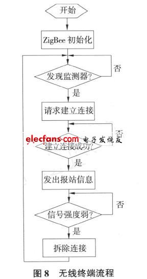
The bus recognizes the station name according to the station identifier sent by the detector, and reports the station via voice and LED screen. After that, the monitor continuously detects the signal strength sent by the wireless terminal, and when it weakens to a certain degree, it considers that the car has left the station and immediately sends relevant information to the monitoring center. The monitoring center stores the information sent by the monitor, judges the road section of the bus according to the received information, and sends the information to the monitor. The monitor displays to the waiting person through the running status indicator.
2 Hardware design
2.1 Monitor
2.1.1 Overall design
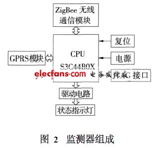
The composition of the monitor is shown in Figure 2. This part is composed of CPU, wireless GPRS communication module, wireless ZigBee communication module, bus running status indicator and other peripheral circuits. The CPU chooses Samsung's S3C44B0X. This processor has the advantages of low power consumption, high performance, and high cost performance. At the same time, it has rich built-in components, which greatly reduces the configuration of components other than the processor in the system circuit, reducing costs and Reduce the complexity of the system. At the same time, it has a large number of I / O ports, which can realize the control of a large number of status indicators. GPRS can not only support intermittent burst data transmission, but also support occasional large data transmission. The data transmission speed is fast, and it is charged according to the flow rate. Therefore, GPRS is suitable for this kind of monitoring system with frequent communication, large data volume and high real-time requirements. The design selects GPRS as the wireless connection between the monitor and the monitoring center. The communication between the monitor and the bus terminal uses ZigBee wireless communication. ZigBee is a wireless network technology with close range, low complexity, low power consumption, low speed and low cost. In the design, ZigBee communication module selects MC13192 of Freescale company, its working frequency is 21405 ~ 21480GHz, adopts direct sequence spread spectrum communication technology, and the data transmission rate is 250kb / s, which meets the design requirements.
2.1.2 GPRS communication module
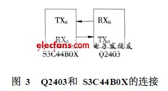
The GPRS module selects Q2403 produced by French WAVECOM company. The module complies with ETSI standards GSM0707 and GSM0705. The download speed is 5316kb / s and the upload speed is 2618kb / s. The module provides an asynchronous serial communication interface that conforms to the V24 protocol, supports encryption algorithms, integrates radio frequency circuits and baseband in one, has stable performance, and can be transmitted quickly and reliably. Q2403 and S3C44B0X are connected through a serial interface, as shown in Figure 3.
2.2 Wireless terminal
The wireless terminal is mainly composed of an audio playback module, a button response circuit, a wireless ZigBee communication module, and an LED screen display module, as shown in Figure 4. The audio playback module is responsible for recording and playing voice station information.
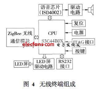
The key response circuit is responsible for responding to the key operation of the bus driver.
2.2.1 ZigBee wireless communication module
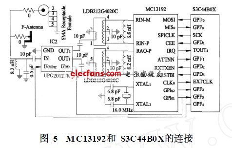
Because the RF signal of MC13192 adopts the differential method, and the inverted F-type antenna is a single-ended antenna, a balanced / unbalanced impedance conversion circuit needs to be used between the chip and the antenna to achieve the best transmission and reception effect.
UPG2012TK and balun circuit special chip LDB212G4020C are used in the circuit. UPG2012TK is a gallium arsenic single-pole double-throw (SPDT) RF switch manufactured by NEC for mobile phones and other L-band applications. Its operating frequency is 015 to 215 GHz, with very low insertion loss and high isolation performance. The connection of MC13192 and S3C44B0X is shown in Figure 5.
2.2.2 LED screen display module
The LED dot matrix screen in the design is composed of 4 LED dot matrix modules. The module needs anode and cathode to control together, and its behavior is anode, and the column is the cathode. Therefore, the LED dot matrix screen drive circuit is divided into row drive circuit and column drive circuit. Part of the design, as shown in Figure 6. The row drive circuit uses 16 8050D NPN transistors and 16 pull-up resistors to complete the drive. The column drive circuit is driven by 16 S8550D PNP transistors and 16 pull-up resistors.
Therefore, the distortion is small, the use is convenient, no special voice development tool is needed, and the cost is low. The keyboard adopts independent keyboard, and the driving chip adopts ZLG7290. The RS232 communication part is completed by MAX233A. The reset part is realized by professional reset circuit chip IMP811.
  
Also known as R134a gas. Under normal temperature for the odorless and colorless gas. Boiling point -26.5 ° C, the freezing point -101 ° C 1.202g/cm3 liquid density. Critical temperature 100.6 ° C Critical pressure 40.03 × 10⁵. Low toxicity, and flame resistant, low chemical reactivity and high stability. PCE fluoride can be obtained CFC-113, via isomerization, fluoride and hydrogen obtained; PCE or fluorinated obtained HCFC-123 and then by fluoride and hydrogen obtained; TCE also as the raw material, fluoride in HCFC-133a, and fluoride system in the product. In refrigeration systems, medical and certain spray foam application is CFC-12 is the preferred alternative.
Small Can Refrigerant,R134A Refrigerant Gas,Small Can R134A,Refrigeration Gas R134A
ZHEJIANG ICE LOONG ENVIRONMENTAL SCI-TECH CO.,LTD. , https://www.china-refrigerantgas.com