In view of the shortcomings of previous electronic blood pressure monitors, a design of an intelligent electronic blood pressure monitor based on a programmable system on chip (SOPC) is introduced. The method of blood pressure measurement uses the oscillometric method based on the inflation process. The system uses Cyclone II series low-cost FPGA, and embedded NNIOS II soft core as the core processor, can complete automatic blood pressure measurement, information display, data storage, view and delete historical data and other functions. Due to the use of FPGA, the design of the circuit is simplified, the reliability and stability of the system are improved, and the system has a strong scalability, which is beneficial to the upgrade of the system.
Blood pressure is an important physiological parameter that reflects the state of the cardiovascular system, and proper blood pressure is a necessary condition for maintaining the normal metabolism of the human body. With the continuous improvement of people's living standards and the aging of the city, people's awareness of self-care has gradually increased. Electronic sphygmomanometers have the advantages of low cost, miniaturization, and high degree of automation. People's favor. SOPC (Programmable System on Chip) is a flexible and efficient SOC solution proposed by Altera. Using programmable logic technology to put the entire system on a piece of silicon, called SOPC. It can perfectly combine MCU, DSP and FPGA, and has very good development prospects.
1 Principle of human blood pressure measurement
1.1 Blood pressure measurement
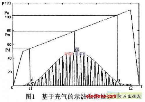
There are many blood pressure measurement methods, the most commonly used noninvasive blood pressure measurement methods are Korotkoff sound method and oscillometric method. The design adopted in this paper is based on the oscillometric method of inflation. Inflation measurement based on the oscillometric method happens to be the reverse process of deflation measurement. As shown in Figure 1, during the pressure increase (inflation), the static pressure and the oscillating wave of gas in the cuff are detected. The oscillating wave originates from the Pulsating. When the pressure is low, before the cuff static pressure is less than the diastolic pressure Pd, the arterial wall has fully expanded during the diastolic period, and the rigidity of the wall has increased, so the amplitude is maintained at a small level. With the increase of pressure, when the cuff pressure is higher than the systolic pressure Ps, the artery is compressed, and at this time, a small oscillation wave appears due to the impact of the proximal pulse; when the cuff static pressure is equal to the average pressure, the amplitude reaches the maximum Value; the cuff static pressure corresponding to the envelope of the oscillating wave indirectly reflects the arterial blood pressure.
1.2 Heart rate calculation
Heart rate refers to the number of times the heart beats per minute. Since the heart and the pulse are consistent, the heart rate can be measured while measuring the blood pressure. The heart rate measurement is to determine the peak value of the pulse wave, and then calculate the heart rate based on how many pulse waves are measured within a certain period of time.
2 SOPC system hardware design
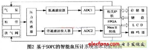
The hardware design block diagram of the SOPC system is shown in Figure 2.
2. 1 SOPC system circuit
This part of the circuit is composed of FPGA chip, memory and other peripheral components, and is the core part of signal processing. The embedded microprocessor system including CPU, memory interface and I / O peripherals is constructed by the SOPC Builder hardware development environment. After completing the system design, you can use SOPC Builder to generate the system. The following figure shows the system content configuration built in SOPC Builder.
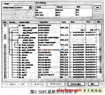
The EPCS device controller core is added to the SOPC system. The purpose of this is to make full use of system resources, solidify FPGA configuration data and Nios II software programs into the EPCS chip, and save more space for the Flash chip. Store measurement results. At this time, the reset address of the Nios II processor should be set to the base address of the EPCS controller. When the system is reset, the program solidified into the EPCS chip will be automatically downloaded to the SDRAM to run.
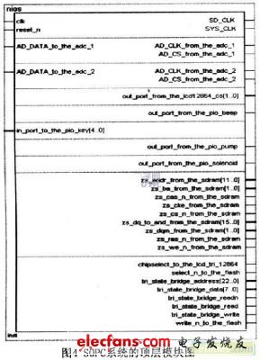
Figure 4 is the top-level module diagram of the SOPC system generated by the SOPC Builder hardware development environment.
2.2 Pressure measuring circuit
2.2.1 Selection of pressure sensor
The pressure sensor of this design is the MPXV5050GP pressure sensor produced by Motorola. It contains signal op amp inside, has signal adjustment function, has good linearity, can directly convert the pressure of arterial blood to the blood vessel wall into an electrical signal of 0.2 to 4.7V, and the corresponding blood pressure value is 0 to 375mmHg. It closely matches the design requirements of the sphygmomanometer.
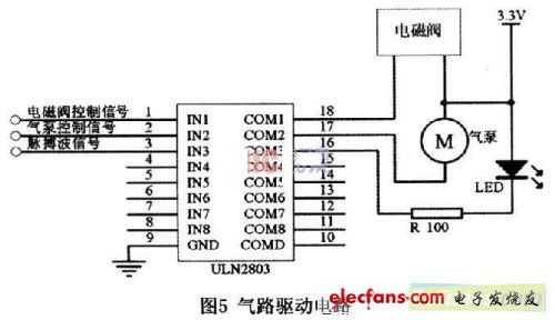
2.2.2 Design of driving circuit
The signals to control the operation of the air pump and the solenoid valve are issued by the FPGA. The working drive current required by the air pump is 450mA, and the solenoid valve is 75mA. The FPGA digital I / O output current cannot meet the requirements. Therefore, in order to provide suitable driving current for the air pump and the solenoid valve, the Darlington tube array ULN2803 drive circuit is used to drive the air pump and the solenoid valve to work. The ULN2803 can output a current of 500mA. The first and second paths of the ULN2803 are used to drive the solenoid valve and the air pump, and the third path drives an LED to indicate the pulse wave signal. As shown in Figure 5.
2.3 Extraction of sensor output signal
The signal from the pressure sensor is a mixed signal of the oscillating signal of the pulse wave and the static pressure signal, and it is also mixed with high frequency interference, direct current or low frequency components from the outside. We divide the mixed signal into two parts. One part undergoes A / D conversion after a low-pass filter to extract the cuff pressure signal, and the other part passes the band-pass filter and amplifying circuit to obtain amplified pulse wave data before sending. Into the A / D conversion module. The specific circuit of the signal extraction part is shown in Figure 6.
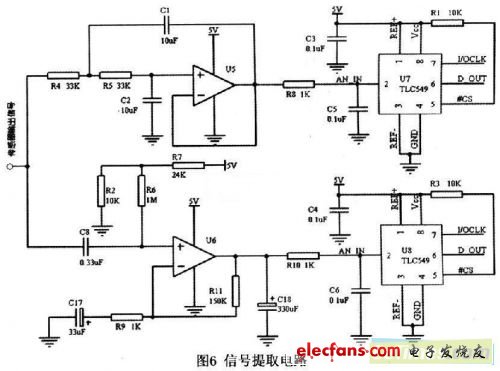
Here, a second-order low-pass Butterworth filter with a cutoff frequency of 0.48 Hz is used, and the low-pass filter gain is set to 1, which can minimize the error amplification. Using an active filter with signal amplification capability to extract the pulse wave signal, the passband frequency range is designed to be 0.48 to 4.8 Hz. After the pulse wave signal is amplified and filtered, the maximum amplitude should be as close as possible to the upper limit of the A / D conversion module, which helps to improve the accuracy of the collected data.
Since the A / D conversion is required for the static pressure signal and the pulse wave signal, two sampling channels are required. The blood pressure of the brachial artery of the human body, the systolic blood pressure is generally in the range of 95-140mmHg, the average value is 110-120mmHg, the diastolic blood pressure is 60-90mmHg, the average value is 80mmHg, considering the conditions of hypertension and other diseases, the measurement range of the blood pressure meter should be Within 0 ~ 250mmHg, the requirement for A / D converter is at least 8 bits (28 = 256).
2.4 Keyboard circuit and display circuit
This system uses 1 button as the system reset switch and 5 buttons as the system operation keyboard, which respectively complete the functions of measuring blood pressure, viewing records, flipping records, flipping records and deleting records. The display part adopts 128 & TImes; 64 dot matrix LCD display, which has the characteristics of easy operation and friendly interface.
PTFE tapes, also known as thread seal tapes, are commonly used within the plumbing industry as a way to enhance the seal between two pipes. When you think about screwing two pipes together you can see that this will not provide the tightest of seals, especially when water or air tight seals are desired. This is where PTFE tape comes into play, as this type of tape fills in the spaces left behind in the threading in order to create the tightest seal possible.
PTFE Fabric With Silicone Adhesive
Strong Adhesive Tape,Silicon Tapes,Silicone Fabric,PTFE Fabric With Silicone Adhesive
TAIZHOU YAXING PLASTIC INDUSTRY CO., LTD , https://www.yaxingptfe.com