Design of traffic signal control system using FPGA

With the rapid development of the social economy, traffic congestion caused by a significant rise in vehicles has become increasingly severe. As a crucial component of the traffic management system, traffic lights play a vital role in managing the interaction between vehicles, pedestrians, and roads, ensuring smoother and safer urban mobility. EDA (Electronic Design Automation) is a technology that utilizes powerful computers to process design files created using hardware description languages like HDL (Hardware Description Language), enabling automatic realization of electronic circuit functions. The ultimate goal of using EDA in electronic system design is to develop Application-Specific Integrated Circuits (ASICs). These circuits serve as the physical platform for implementing specific functions and technical requirements of electronic systems through EDA tools. Among the key devices used for this purpose, Field-Programmable Gate Arrays (FPGAs) are widely adopted due to their flexibility, efficiency, cost-effectiveness, ease of maintenance, and high reliability. **1. Design Requirements** **1.1 Application Background** 
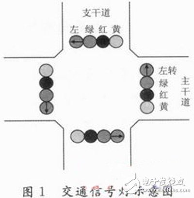
This project involves a crossroad where a main road intersects with a branch road. The main road runs east-west, while the branch road runs north-south. To ensure safe and efficient vehicle passage, red, green, and yellow signal lights, along with left-turn signals, are installed at each entrance of the intersection, as illustrated in Figure 1.

FPGA-based traffic signal control system

**1.2 Requirements** (1) When the main road's green light is on, the red light is off, and vice versa. They alternate to allow passage. The main road is allowed to pass for 40 seconds, while the branch road is allowed for 30 seconds. During the green light period, the first 10 seconds are for the left-turn signal, followed by 5 seconds of yellow light, with the remaining time being for straight movement. (2) A countdown display function should be implemented. (3) The system must have an overall reset function, allowing the counter to start from the initial state and activate the corresponding indicator lights. **2. System State Analysis** Analyzing the design requirements, the sequence of changes in the traffic lights for both the main and branch roads is shown in Figure 2. The state transition is detailed in Table 1.

FPGA-based traffic signal control system

**3. System Structure Design** Based on the requirements, the system structure is designed as shown in Figure 3. A clock pulse is generated by dividing the crystal frequency. The main controller receives the clock signal and transitions between states accordingly, outputting the time for each state. The signal light controller manages the lights on the main and branch roads based on the state information provided by the main controller. Since the time signal is in real-time format, a quantization module is needed to convert it into two sets of BCD codes for the digital display.

FPGA-based traffic signal control system

**4. VHDL Design Implementation** To facilitate system implementation, each module is designed using VHDL. The main controller acts as a counter, receiving a second pulse signal with a cycle of 70. After counting to 1, the counter resets upon the next clock pulse, restarting the cycle. The system reset signal ensures the counter returns to state S0 and begins counting again. Below is the VHDL code for the main controller, where `clk` and `rst` are the clock and reset signals, `state` represents the current state, `seg7a` and `seg7b` indicate the countdown times for the main and branch roads, and `temp` is an internal variable.

FPGA-based traffic signal control system

**5. Result Simulation** Each module was connected using Quartus II software, compiled, and simulated successfully. After pin allocation, the configuration file was downloaded to the KX_7C5TP FPGA development board, and the system operated correctly, confirming the validity of the entire design. The simulation results are shown in Figures 4 and 5.

FPGA-based traffic signal control system

**6. Conclusion** The design of the traffic signal control system using FPGA simplifies the designer’s work by focusing on software tools such as hardware description languages and EDA software. This approach not only enhances design flexibility but also allows for easy modification of signal timing cycles, making it a powerful solution for modern traffic management systems.

Outdoor Rental Stage Events Led Display

Outdoor rental stage event LED displays are large LED screens that are used for outdoor events such as concerts, festivals, and sporting events. These LED displays are designed to be easily set up and taken down, making them ideal for temporary outdoor events.

P2.6/P2.976/P3.91/P4.81/P5 are popular in outdoor rental stage event usage.

Outdoor Rental Stage Events Led Display,Outdoor Concert Stage Background Wall,Outdoor Stage Rental Led Screen,Events Venue Led Screen System

Guangzhou Cheng Wen Photoelectric Technology Co., Ltd. , https://www.cwledwall.com

Posted on