This section explains how to build a basic NIOS II processor system that supports the RT-Thread operating system within Qsys, and further demonstrates an example of creating two static threads with LED blinking functionality. The version of the RT-Thread operating system used is 3.0, the software version is Quartus II 13.0, and the development environment is Windows 7 64-bit. The hardware platform used is the Xiaomeige AC620 FPGA development board, and the embedded processor is the NIOS II.

Steps
Building a NIOS II CPU system that supports the RT-Thread operating system involves configuring the necessary peripherals in Qsys. In addition to the standard NIOS II processor, memory components such as on-chip RAM, SRAM, SDRAM, or DDR2 are required. To support RT-Thread, UART serial interfaces, timer peripherals, and a PLL phase-locked loop must also be included to enable higher frequency operation. Additionally, a wide output PIO is added to drive the LEDs based on the specific hardware setup.
The system includes the following key peripherals:
A PLL clock management unit that provides two clocks with a 90° phase difference—one for the system logic and one for the SDRAM clock.
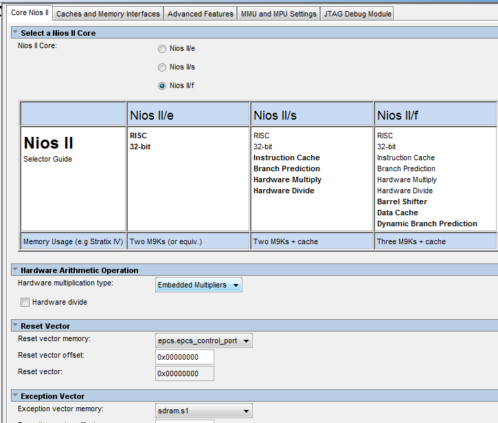
NIOS II processor (fast version selected).
SDRAM controller (16-bit data bus, 12-bit row address, 9-bit column address) used for storing both data and instructions.
EPCS controller for storing firmware information for the FPGA and NIOS II.
UART (RS232) controller for standard input/output, set at 115200 baud rate by default.
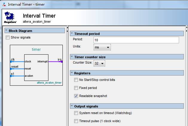
Timer peripheral set to a 10-millisecond interval, which can be modified via software.
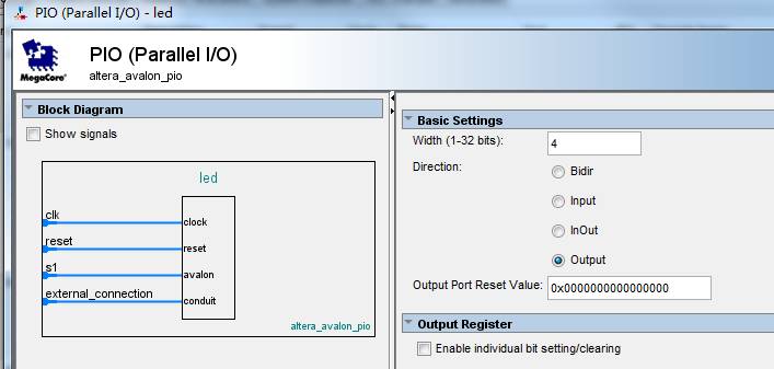
4-bit output PIO connected to four LEDs on the development board.
The image below shows the minimal NIOS II application system built.
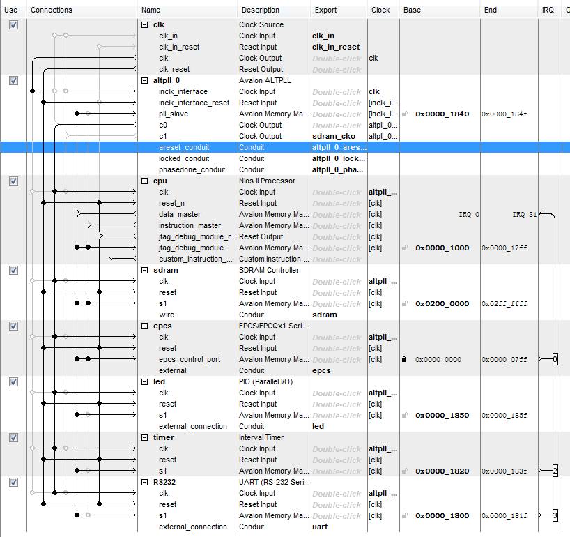
It is important to note that the PIO used for driving the LEDs is named “LED†directly, and the UART is named “RS232†to match the corresponding code in the official RT-Thread BSP files.
NIOS II CPU configuration settings:
Timer parameter settings:
UART controller settings:

LED PIO settings:
Instantiating the CPU system in a Quartus II project
Designing the top-level file
Name the system created in Qsys as "mysystem", generate the HDL file, add the "mysystem.qsys" file into Quartus II, create a new Verilog file, and modify the top-level instantiation code accordingly.
The improved code is as follows:
module ac620_ghrd (
    input wire reset_n,
    input wire clk,
    output wire [11: 0] sdram_addr,
    output wire [1: 0] sdram_ba,
    output wire sdram_cas_n,
    output wire sdram_cke,
    output wire sdram_cs_n,
    inout wire [15: 0] sdram_dq,
    output wire [1: 0] sdram_dqm,
    output wire sdram_ras_n,
    output wire sdram_we_n,
    output wire [3: 0] led,
    input wire uart_rxd,
    output wire uart_txd,
    output wire epcs_dclk,
    output wire epcs_sce,
    output wire epcs_sdo,
    input wire epcs_data0
);

mysystem u0 (
    .clk_in_reset_reset_n (reset_n),
    .clk_in_clk (clk),
    .sdram_addr (sdram_addr),
    .sdram_ba (sdram_ba),
    .sdram_cas_n (sdram_cas_n),
    .sdram_cke (sdram_cke),
    .sdram_cs_n (sdram_cs_n),
    .sdram_dq (sdram_dq),
    .sdram_dqm (sdram_dqm),
    .sdram_ras_n (sdram_ras_n),
    .sdram_we_n (sdram_we_n),
    .led_export (led),
    .uart_rxd (uart_rxd),
    .uart_txd (uart_txd),
    .sdram_cko_clk (sdram_clk),
    .epcs_dclk (epcs_dclk),
    .epcs_sce (epcs_sce),
    .epcs_sdo (epcs_sdo),
    .epcs_data0 (epcs_data0),
    .altpll_0_phasedone_conduit_export (),
    .altpll_0_locked_conduit_export (),
    .altpll_0_areset_conduit_export ()
);

endmodule
Setting EPCS pin functions
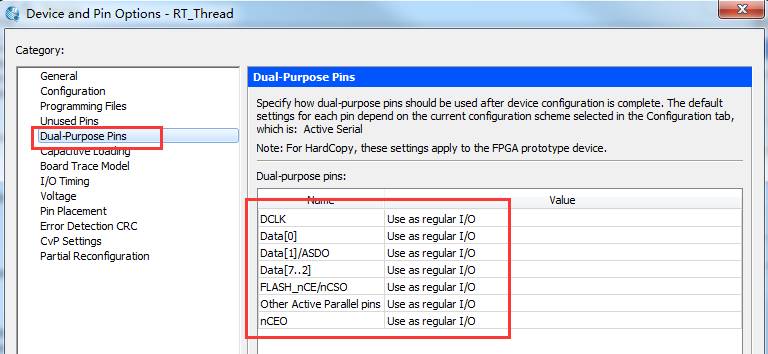
Assign pins according to the AC620 FPGA development board's pin assignment table or silkscreen. Ensure all IO levels are set to 3.3LVTTL to properly drive the SDRAM. Also, set the EPCS function to regular IO in Quartus.
Adding an SDC constraint file
When working on NIOS II-based SOPC projects, it’s essential to add an SDC constraint file to define the system clock, ensuring proper layout and timing. Without constraints, the system may not operate correctly or may fail to download software. The SDC file in this example is simple:
set_time_format -unit ns -decimal_places 3
create_clock -name {clk} -period 20.000 -waveform {0.000 10.000} [get_ports {clk}]
derive_pll_clocks
After adding the constraint, compile the entire project and generate the .sof file.
Creating a NIOS II application engineering template
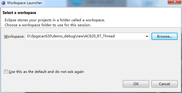
Open the NIOS II software development tool integrated with Quartus II (based on Eclipse), and switch the workspace to the Quartus II project directory.
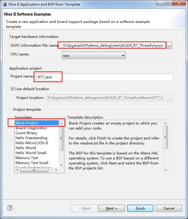
Create a new blank template project and a BSP project, making sure the path to the sopcinfo file is correct.
Porting the RT-Thread Operating System
Download the RT-Thread source code from Git: https://github.com/RT-Thread/rt-thread. Select the master branch and download the zip file. This file can also be obtained from the example provided.
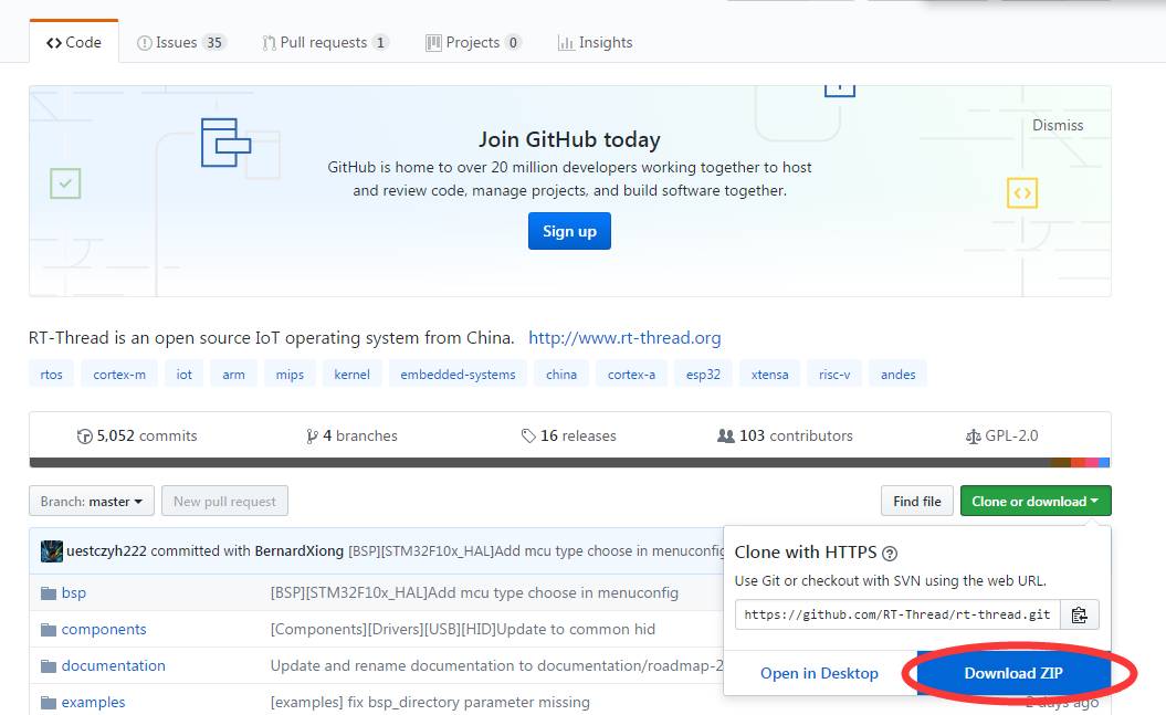
After downloading, the file name is “rt-thread-master.zipâ€.
Porting the RT-Thread source code
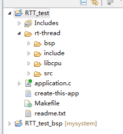
Create a new folder called “rt-thread†under the RTT_Test project, add the “src†and “include†folders, and include the “libcpu†folder for NIOS support. Only the NIOS part is needed, so other CPU architectures can be ignored. After adding the source code, copy the .c and .h files from the “bsp/niosii†directory into the project. Move the “application.c†file to the root of the software project since it contains the main function.
Setting the header file search path
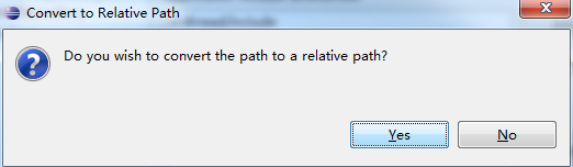
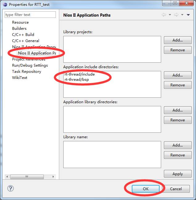
After adding all the files, set the header search path in the software settings. Right-click the RTT_Test project, select Properties, go to Nios II Application Paths, and add the “include†and “bsp†folders. Confirm the changes. If a relative path prompt appears, select Yes.
At this point, all requirements for running the RT-Thread operating system have been met.
Disabling FINSH support
Open the “rtconfig.h†file in the “rt-thread/bsp†directory, locate line 80, and comment out the line “#define RT_USING_FINSH†using “//†to disable the FINSH feature.
Running the RT-Thread Operating System
Compiling and running the program
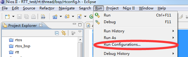
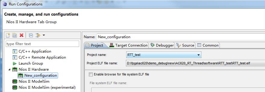
Fully compile the project (Ctrl + B). If no errors occur, an elf file will be generated, which can be downloaded to the NIOS II CPU. Click “Run > Run Configurations†to open the download interface.
Create a new hardware run configuration, select the RTT_Test project, switch to the Target Connection tab, and refresh to confirm that the USB Blaster has detected the CPU. Before this, download the .sof file generated by Quartus II to the development board and connect it via Micro USB cable. Open the serial debugging tool, find the corresponding serial port, and set the baud rate to 115200 with ASCII reception.
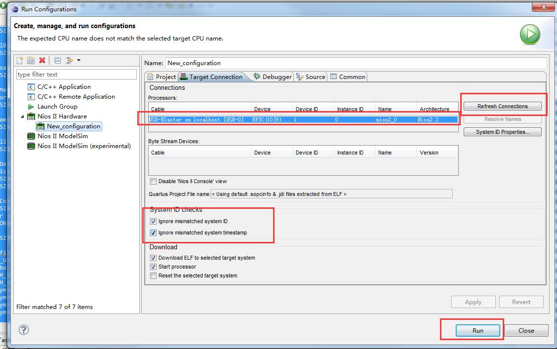
Check the “Ignore system id and timestamp†option and click Run to start the software download.
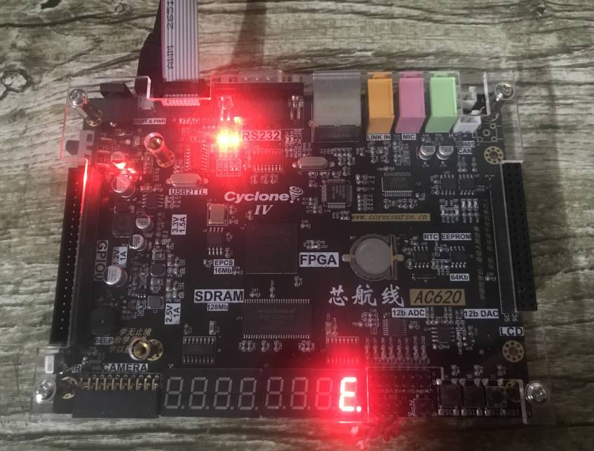
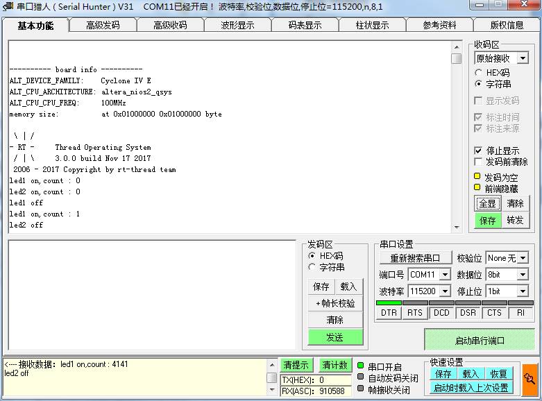
Experimental Results
After the download completes, you should see system messages printed in the serial debugging assistant, and the four LEDs on the development board should blink in a cyclic pattern.
High quality product originates from innovative breakthrough in product design. Based on continuous tracking of advanced technology developments at home and abroad, Securing by independent R & D products and designing with the highest quality product, Longxc Smelted the industry's first professional dental Medical Power Supply, first medical adapter with LED, first slim ultra small 90W adapter and so on.
Breast Pump Adapter,Biochemical Power Supply,Biochemical Adapter,Medical Atomizer Adapter
Shenzhen Longxc Power Supply Co., Ltd , https://www.longxcpower.com