Current sensing in automotive applications includes controlling the current through the solenoid and the injector. For example, in diesel injection, we quickly increase the induction injector current to 20 amps with a voltage of 48V or higher. Once 20A is reached, the current sense circuit provides a feedback signal to the control circuit to keep the injector current at 20A. Current sensing typically enhances important performance or characteristics. The electric window system is a good example of the advantages of current sensing technology. Since the motor torque is proportional to the current, the motor will stop working when the torque is too large. For example, if the person's arm is stuck on the power window or the mechanical system fails, the motor will stop working. Current detection method
This article refers to the address: http://
Current sensing is available on the low or high side of the load or power supply. The common mode voltage is the voltage on the shunt (not the differential voltage on the shunt) and zero volts on the low side. The low-voltage side detection is the simplest and the most basic amplifier circuit can be used. The difficulty in low-voltage side detection is that low-voltage side detection can affect the grounding of the system, and more lines may need to be added, and this practice is usually not conducive to fault diagnosis. The high-side shunt amplifier in Figure 1 can detect very low differential voltages on very high supply voltages (typically 100mV or less), typically 13.8V in automotive applications. However, if it is an unconditioned battery line, it will be affected by transients: if you accidentally misplace the battery, it will appear –13.5V, if there is load dump or inductive kickback, then the maximum moment It can be changed to 72V. It is conceivable that the amplifier is usually powered by a single 5 to 12V supply (a 5V supply is increasingly common), which requires the input pin of the amplifier to be connected to the common-mode potential, well beyond the limits of the amplifier's power rail.
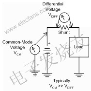
Figure 1. Common-mode voltage is the main problem in high-side current detection. The old-fashioned shunt detection circuit is based on a differential amplifier, that is, an operation amplifier with four resistors around to set the gain and provide a differential input. These resistors allow the op amp to accept a common-mode voltage that exceeds its rail. However, this also brings down some of the following negative problems: First, the circuit must be configured as an attenuator, and the gain is restored in the subsequent op amp stage. As shown in the IC block diagram in Figure 2A, the gain of the op amp is multiplied. The bias and drift of the first amplifier reduces overall performance. The second is to use a high common-mode voltage differential amplifier to increase the resistor network so that it can still accept a higher common-mode voltage while still providing only unity gain. The effect of the high common-mode differential amplifier is that the noise gain of the op amp is proportional to the common-mode attenuation. The differential amplifier structure shown in Figure 2B uses a 20:1 internal common-mode attenuation, which makes the amplifier biased. Set, drift, and noise are up to 20 times larger than the op amp itself. In addition, larger input resistances can also cause higher noise.
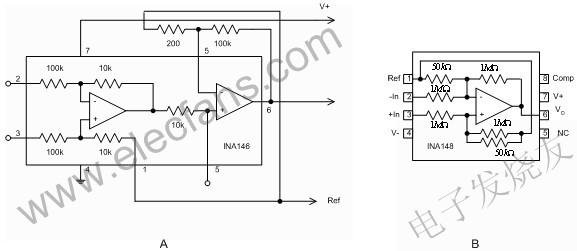
Figure 2 Resistive High Common-Mode Voltage Differential Amplifier Current Shunt Monitor for Vehicle Current Detection is a high common-mode voltage differential amplifier designed for shunt current detection to solve the limitations of resistive differential amplifiers. The main difference between a current shunt monitor and a differential amplifier is that its common mode voltage function typically extends only to positive voltages, while some current shunt monitors allow common mode grounding. This will lead to more derivation, which we will talk about later. The common mode voltage function also allows expansion to a negative voltage. The current shunt monitor is designed to operate from a single supply voltage from the start, typically at a minimum voltage of 2.7V. Figure 3 shows two types of current shunt monitors, which are divided into current output type shunt monitors and voltage output type shunt monitors. Current output shunt monitors typically have low quiescent current and require an external output resistor to allow the end user to set the gain. The voltage output device uses a fixed gain and does not require additional components.
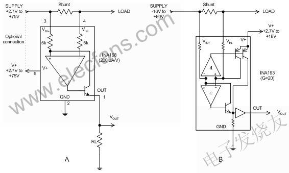
Figure 3 Two types of current shunt monitors include: A) current output type shunt monitors and B) voltage output type shunt monitors. General technical requirements for in-vehicle applications
On-board current sensing is divided into two main types: one is connected directly to the battery, and the other is connected by a protection circuit that limits transient offset. This condition affects the common mode voltage rating requirements on the current shunt monitor. The maximum voltage of the 12V electronic system on the vehicle is 14.4V, but the transient voltage on the battery bus device can reach up to 75V, and even the battery can be pole-changed. We also have to consider another common mode situation: the shunt of the power line is turned on, and the ground is shorted. At this time, the common mode voltage is zero. The current must flow when it is tested, that is, the amplifier must operate normally at zero common-mode voltage. Finally, we might consider the case of a pulse width modulation (PWM) solenoid driver as shown in Figure 4. In this example, the battery voltage is reached when the top of the solenoid is open. When the switch is turned off, the voltage will return to the negative level of the diode voltage drop. This requires the current shunt monitor to operate at common mode voltages as low as –2V.
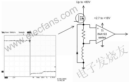
Figure 4 Current sensing should be performed in PWM applications, even during retrace periods where the common-mode voltage drops to a negative voltage of the diode voltage drop. Current comparison
In many applications, the current should be compared to a setpoint. In general, current shunt monitors, comparators, and reference voltages are required for current comparison. In addition, the ideal comparator output should be well compatible with most common logic circuits. Figure 5 shows an example of current comparison. In this example, the current is compared to a simple single voltage junction using the TI INA200 Series Current Shunt Monitor and Comparator. R1 and R2 form a voltage divider to set the voltage junction based on the built-in 0.6V voltage junction of the INA200 series comparators. (The gain of the INA200 series is very characteristic: the gain of the INA200 is 20, the gain of the INA201 is 50, and the gain of the INA202 is 100.)
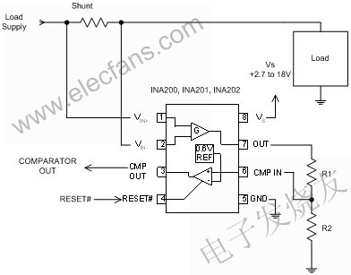
Figure 5. Simple single-voltage junction current comparison Some systems require more than one current limit level. For example, the system uses a lower current limit as an indicator of an impending failure, and a higher limit as a sign of shutting down the system. The INA206-INA208 series of current shunt monitors use two comparators to achieve these functions. Some systems use a delayed output for lower limits to avoid unnecessarily triggering a transient offset after exceeding the minimum limit. The circuit in Figure 6 feeds the output of the INA206 Current Shunt Monitor section back to the two comparators, which generates an active low output alarm and provides the proper polarity to turn off the MOSFET buffer path. Figure 6 shows the circuit where the current is compared to two voltage junctions. The lower voltage node activates the alarm output and we can configure it with an appropriate delay circuit to avoid false transient triggering. The lower voltage junction has a built-in threshold of 0.6V at the comparator input. Q1 buffers the higher voltage node output, turns off the power through the power switch MOSFET, and enables Q2 if the current exceeds the upper limit. The higher voltage junction uses the 1.2V reference voltage of the INA206, and the INA206 has a latching function that avoids oscillations at voltage nodes that do not have a latch function.
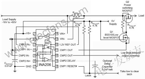
Figure 6 In this two-level current comparison circuit, the low-level delay output alerts the impending overload, and the upper limit of the latching function is enabled to turn off the load supply.
Ebike Battery,Downtube Battery,Cylinder Lithium Battery,Power Battery With Usb Port
ZHEJIANG TIANHONG LITHIUM-ION BATTERY CO.,LTD , http://www.tflbattery.com