Foreword
In recent years, the power steering system has become the standard setting for some cars, and about half of the cars in the world use power steering. With the development of automotive electronic technology, some cars currently use electric power steering (EPS), which has improved the economy, power and mobility of automobiles. EPS uses the power generated by the motor to assist the driver in power steering. It is generally composed of a torque (steering) sensor, an electronic control unit, an electric motor, a speed reducer, a mechanical steering gear, and a battery power supply. When the car is turning, the torque (steering) sensor will "feel" the torque of the steering wheel and the direction of rotation. These signals will be sent to the electronic control unit through the data bus. The electronic control unit will be based on the transmission torque, the direction of rotation, etc. The data signal sends an action command to the motor controller, so that the motor will output a corresponding amount of rotating torque according to specific needs, thereby generating power steering. If it does not turn, the system will not work and is in a dormant state. Due to the working characteristics of electric power steering, the driver will feel a better sense of direction and more stable at high speeds. And because it does not work when it is not steering, and only needs electricity and no hydraulic pressure, it can save about 80% energy under various driving conditions with the traditional power steering system, improving the running performance of the car. It has been rapidly promoted in recent years and is also the development direction of the power steering system in the future.
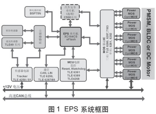
Figure 1 shows a typical electric power steering system, the core of which is a motor frequency conversion speed control system. Because PMSM has the characteristics of simple structure, small size, light weight, low loss, high efficiency, etc. Compared with DC motors, it does not have mechanical commutators and brushes. Compared with asynchronous motors, it does not require Reactive excitation current, so the power factor is high, the volume is small, the current and stator resistance losses are small, and the rotor parameters can be measured, the fixed rotor air gap is large, and the control performance is good. It is the first choice for automotive electric power steering systems.
The vector control of the permanent magnet synchronous motor generally controls the stator current or voltage by detecting or estimating the position and amplitude of the motor rotor flux. In this way, the torque of the motor is only related to the flux and current, which is similar to the control method of the DC motor , You can get high control performance. For permanent magnet synchronous motors, the rotor flux position is the same as the rotor mechanical position, so that by detecting the actual position of the rotor, the rotor flux position of the motor can be known, so that the vector control of the permanent magnet synchronous motor is compared to the vector control of the asynchronous motor. Simplified. When high precision, high dynamic performance and small volume are required, the application of PMSM motor servo system has obvious advantages. This article specifically discusses the design of a PMSM motor servo system for EPS systems. The system uses XC164CM as the core control chip of the EPS system, and uses the stator field orientation principle (FOC) to achieve servo control of the permanent magnet synchronous motor. The experimental results prove that the system is reasonable in design, reliable in performance, and very targeted.
XC164CM and CAPCOM6E
XC164CM is a new variant of the C166 series of single-chip microcomputers widely used at present, which is based on the enhanced C166S V2 structure and is superior to the existing 16-bit solutions. XC164CM has strong DSP performance and advanced interrupt processing, plus a variety of efficient and flexible peripherals and high-performance on-chip Flash, making it an ideal choice for industrial and automotive application equipment control. Its flexible intelligent PWM unit CAPCOM6E provides PWM control of various motors such as AC motors (AC), brushless DC motors (BLDC) and switched reluctance motors (SRM). The high-speed, high-resolution and synchronous trigger ADC can quickly and accurately convert complex analog environment variables. The high-speed TwinCAN module with automatic gateway function can realize an efficient networked solution. The XC164CM package is P-TQFP-100, and the block diagram is shown in Figure 2.
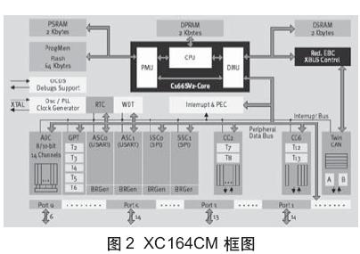
Compared with C166, C166S V2 has many advantages. First, it uses an enhanced Harvard structure (program memory and data memory have their own multi-bandwidth buses), has a single-cycle instruction set, and has a 40MIPS instruction execution speed at a 40MHz CPU clock. Secondly, it not only has a 5-level instruction pipeline, but also adds a 2-level prefetch instruction pipeline, which has unparalleled program branch prediction and judgment capabilities, thereby achieving zero-cycle program jumps. In addition to its high-speed hardware multiplying / dividing unit, it also integrates a single-cycle multiply-add unit (MAC) unit, which has a powerful DSP function (including DSP instruction set), which greatly improves its computing power. The matching DSP function library can enable users to quickly and conveniently implement various DSP operations such as FIR, IIR, FFT, etc. C166S V2 also integrates an on-chip debug system (OCDS) with JTAG interface.
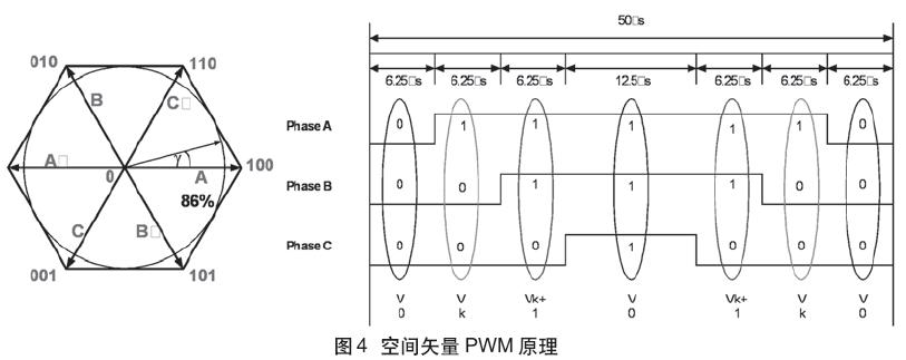
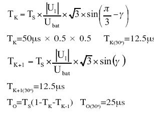
The intelligent PWM unit CAPCOM6E of XC164CM is shown in Figure 3. It can generate various types of PWM waveforms, such as SPWM, Space Vector PWM (SVPWM), etc. This system uses SVPWM, and its generating principle is shown in Figure 4. The 8 possible switching states form 6 possible magnetic field directions (plus two zero vectors). The magnetic field vector can reach all points in the hexagon (the operating area of ​​the inverter) without exceeding the hexagon. The PWM switching frequency is 20KHz.
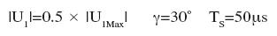
The time calculation formula (30o) is:
Field-oriented (FOC) control and its implementation
In order to establish the mathematical model of the rotor shaft (d, q axis) of the permanent magnet synchronous motor, the following assumptions are made:
· Ignore the saturation of the motor core;
· Excluding the eddy current and hysteresis loss of the motor;
· The rotor has no damping winding.
Under the above assumptions, the motor voltage equation expressed in the rotor reference coordinates (axis) is as follows:
Stator voltage equation
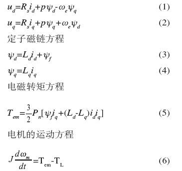
Where: ud, uq is d, q-axis voltage; id, iq is d, q-axis current; Ld, Lq is the equivalent inductance of stator inductance under d, q-axis; Rs is stator resistance; we is rotor electrical angular velocity Yf is the flux linkage of the rotor excitation magnetic field chain passing the stator winding; p is the differential operator; Pn is the number of motor pole pairs; wm is the rotor mechanical speed; J is the rotational inertia; TL is the load torque.
The above equation is obtained through the transformation of a, b, c coordinate system to d, q rotor coordinate system. Here, the rotor axis is taken as the d-axis, and the q-axis leads the d-axis by an electrical angle of 90 ° along the rotation direction. The coordinate transformation is as follows:
Clark transformation
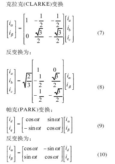
From the rotor coordinates, the stator current can be divided into two parts, namely the torque current iq and the excitation current id. Therefore, in vector control, id = 0 is usually used to ensure that the maximum output torque is obtained with the smallest current amplitude. At this time, the motor torque expression of equation (5) is 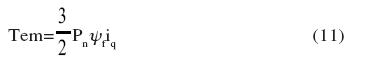
It can be seen from equation (11) that Pn and yf are internal parameters of the motor, and their values ​​are constant. In order to obtain a constant torque output, as long as iq is controlled to be a fixed value. From the analysis of the d and q axes above, the direction of iq can be determined by detecting the rotor axis. Therefore, the vector control of the permanent magnet synchronous motor is greatly simplified. The field-oriented control (FOC) of the entire PMSM motor is shown in Figure 5. 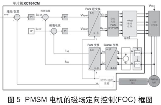
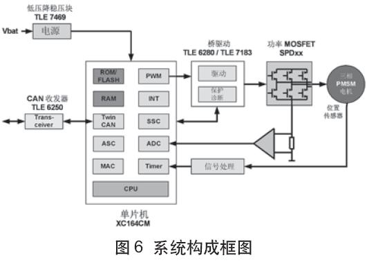
The hardware of the PMSM motor control system with XC164CM as the core is shown in Figure 6. The control circuit of the entire system consists of XC164CM. As the control core, XC164CM receives external information to judge the working mode of the system, and converts it into the switch signal output of the inverter. This signal directly drives the power MOSFET to supply power to the motor through the drive circuit.
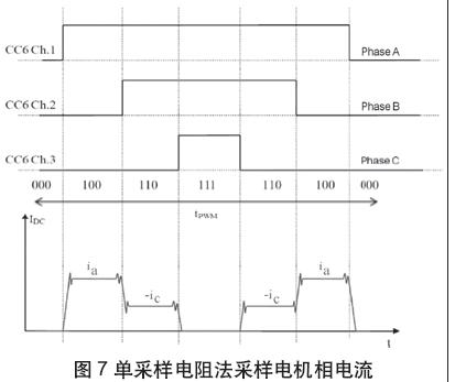
Current sampling circuit
Usually the vector control of PMSM motor requires sampling the stator current of two-phase motor, such as ia and ic. However, this system uses a single sampling resistor to sample the DC bus current, and combines with the actual output PWM combination to infer the actual motor stator phase current. The ADC of XC164CM can be set to be triggered synchronously by the rising / falling edge of the PWM waveform. Obviously, this method can sample the two-phase current twice in a PWM switching cycle, as shown in Figure 7.
Rotor position detection circuit
The motor rotor position feedback uses an incremental photoelectric encoder with a resolution of 2000 pulses / revolution, where the A and B signals differ from each other by 90 ° (electrical angle). XC164CM can be obtained by judging the phase and number of A and B The direction and speed of the motor. Collect these signals to judge the position of the motor rotor and the motor speed.
software design
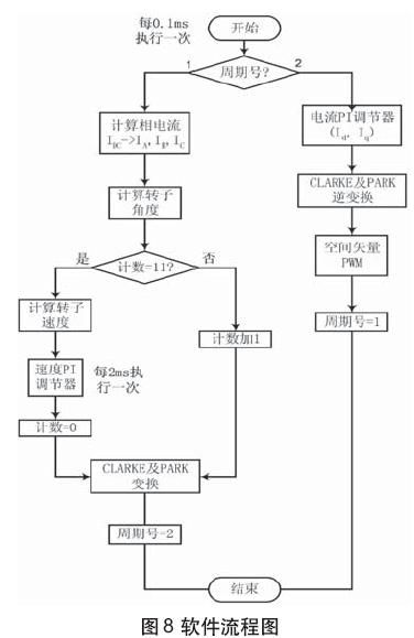
The system software consists of two parts: the main program and various functional modules such as current sampling, speed and position calculation, speed PI control, current PI control, CLARKE and PARK transformation and inverse transformation, space vector PWM and so on. In the main program, complete system initialization, I / O interface control signals, setting of each control module register in XC164CM, etc., and then enter the infinite loop program. Each function module is executed at a certain time interval based on the PWM cycle. The entire software flow is shown in Figure 8.
The actual time spent measuring each major functional module is shown in Table 1.
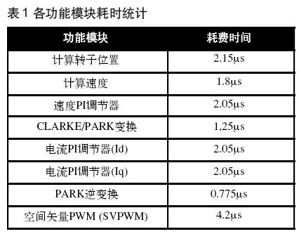
Simulation and experimental results show that the system has a faster dynamic response and higher control accuracy, and can fully meet the requirements of the electric power steering system. It is particularly worth noting that the powerful DSP function of XC164CM can complete a series of complex operations in a short time, which not only guarantees the real-time performance of PMSM motor vector control, but also ensures the smooth implementation of other tasks of the EPS system.
Conclusion
This article discusses in detail the technical key of the electric power steering system-PMSM motor field-oriented control system. The system hardware uses XC164CM as the controller. The circuit design is simple and compact, which meets the system requirements. At the same time, the fully digital control has greatly improved the control accuracy, function and anti-interference ability of the system. The powerful DSP function of XC164CM, intelligent PWM generating unit and high-performance ADC enable the system to realize high-performance EPS system with only a few circuit components, and it has a good market application prospect. In addition, the rational design of the system software structure also guarantees the real-time and stability of the system.
If you are new to the concept of using an electric kettle, you might be overwhelmed by the variety of electric kettles that are displayed on the store shelves and have difficulty deciding which one would be the best to suit your individual needs or desires. This introduction will give you some basic information about some of the features that are available on various types of electric kettles so that you can make a more informed decision when choosing one for use in your home.
Features:
Spend few minutes to boil : After 5 minutes, hot water will finish for you to drink.
3 protection functions : The on/off button is on the handle, making it easy to turn the kettle off when you pick it up. A concealed heating unit reduces the amount of buildup in the kettle.
It will be a problem when you forget to close the button.Once the water boils the kettle shuts itself off.Do not have to worry about damaging it by letting it run dry. When water runs dry,It will cut the electric by itself.
Multiple Cups: Water can be loaded to 1.8Liter.
Materials :
Food grade stainless steel, more healthy and hygienic. PP handle wieh heat insulation material provides scald resistance. Durable controller performance with 360 degree rotation cordless base design.
OEM & ODM service : Try best to support you during production and provide better after-sales service.Enhance your brand popularity.
Application:
Make a cup of tea.
Boil eggs.
Cook noodles.
Electric Water Kettle
Electric Water Kettle,Aluminium Electric Water Kettle,Mini Electric Water Kettle,Stainless Steel Electric Water Kettle
Guangzhou Taipeng Electrical Appliances Technology CO., LTD. , https://www.kettles.pl