A remote control system for multiple home appliances based on the public telephone network is given, which uses the DTMF signal of the telephone to obtain control commands. This control system has the characteristics of simplicity, low price and practicality, and is more safe and reliable than the general control system. This article also gives the hardware and software flow of this control system.
Keywords: PSTN, dual tone multi-frequency, remote control
1 Introduction
With the development of computer technology and communication technology, remote control technology relying on public switched telephone network (Public Switched Telephone Network, PSTN) is becoming more and more common. At present, the application of more is the cooperation of PC and Modem, which can easily achieve long-distance, large-capacity, high-precision digital data transmission, but the cost of using this technology is higher, it seems to be used in the remote control system of household appliances Very uneconomical. Under normal circumstances, if the controlled terminal is a set of switches or timers, and the control commands are not complicated, you can directly use the ten numeric keys, "*", "#" keys on the dual tone multi-frequency (DTMF) telephone And A ~ D, or a combination of them to achieve. Due to the widespread distribution of the public telephone network and the further popularization of mobile phones, this PSTN-based remote control system is convenient and economical, as long as a device like this is connected to the home phone, no matter where it is, as long as it can dial It can be controlled by the phone at home.
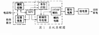
The central processor (MPU) used in this remote control system is the 89C51 single-chip microcomputer, which plays an overall control role on the entire system. The DTMF signal decoder used is MC145436 from Motorola. The filtering characteristics of this system are good, and it can work normally under the background of large noise. In addition, the system is versatile and can be used in other remote control systems with a little modification. The system block diagram is shown in Figure 1.
2 DTMF signal characteristics
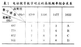
DTMF dual-tone multi-frequency signal is a signal widely used in key telephones (fixed phones, mobile phones), program-controlled switches and wireless communication equipment. It is a group of combined signals formed by superimposing high-frequency signals and low-frequency signals. Both CCITT and China's national standards stipulate the correspondence between the keys of the telephone keyboard and the dual-tone multi-frequency signals as shown in Table 1.
The table shows that any key on the phone keypad is composed of two frequencies that are not in a harmonic relationship with each other, so a set of frequencies corresponding to each key can be uniquely identified. This control system is also designed based on this.
3 DTMF signal decoding circuit
This system uses Motorola's high-performance DTMF receiver MC145436 as the core of decoding, as shown in Figure 2.
After the system starts to work, if the MPU gets a control request (a function of the system software part), it will set P0.0 (set ENB to a high level), and the decoder starts to work, at this time D1, D2, D4, D8 Start to output the decoding result corresponding to Ain pin. This 4bit information will output the result corresponding to the keyboard through the 4/16 decoder (74HC154). See Table 2.
4 Filter-amplified relay drive circuit
The voltage on the user's telephone line is kept at about 48V before going off-hook. After off-hook, the button voltage is about 1.5V. The DTMF signal is included in this voltage. However, under normal circumstances, due to the limitation of the working noise of the decoder, the decoder cannot be decoded directly when used directly. Therefore, it is necessary to filter and amplify the "voice signal" after off-hook. See Figure 3 filter amplifier circuit.
This is an active filter. Since the base current of VT is very small, R3 can be increased to change the voltage division ratio, and a better filtering effect can be obtained without increasing C2.
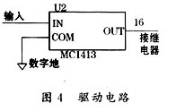
The control of the equipment can only be achieved by closing the relay, but the high level given after DTMF decoding and 74HC154 decoding cannot directly drive the relay. Therefore, this system uses Motorola ’s MC1413 to drive the relay. As shown in Figure 4.
5 Software design and implementation
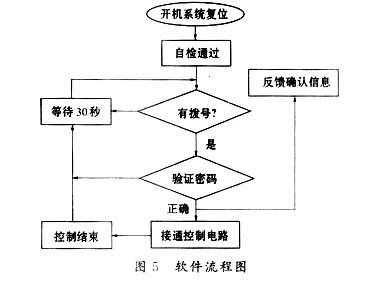
The software part includes four modules: off-hook reset self-test, dial detection and identity verification, control information feedback, and control of the entire system.
The system detects the dialing of the phone by detecting the ringing signal. When the MPU detects a ringing output, it waits for 25 seconds. If the phone is connected, it means that it is in the call use mode at this time. If no one is connected to the phone, then use the software to simulate off-hook, and then enter the password verification state, if it passes the verification, execute the control command.
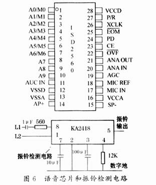
The chip KA2418 with higher integration is selected in the ringing detection circuit, and its output terminal is connected to the P3.0 port of the MPU through level conversion (as an input port to detect ringing). The analog off-hook is modeled on the off-hook circuit of an ordinary telephone, and is completed using the MPU program. Password verification is achieved by comparing the received password (2bit key signal) with the password stored in the MPU. The feedback of the confirmation information is completed by calling the voice information stored in the dedicated voice chip. The voice chip used in this system is ISD2560 (28Pin DIP package), which is one of the ISD series of monolithic voice recording and playback integrated circuits. It is a permanent memory type recording and playback voice circuit. The recording time is 60s, which can be repeatedly recorded and played up to 100,000 times . It uses direct level storage technology, eliminating the need for A / D and D / A converters. Its start address selection is determined by A0 ~ A9, and it can be used to feed back the control results to the controller.
6 Conclusion
The home appliance remote control system implemented using the public telephone network is a convenient and cheap home remote control system. Today, with the increasingly perfect communication network and increasingly popular communication tools, it is a technology worth promoting. The system has a high performance-to-price ratio, and the smart instruments further developed from this system are in line with the future development of intelligent and networked home appliances and have great market development potential.
references
1 Edited by Wan Fujun. Design and development of single chip microcomputer principle system. Hefei: China University of Science and Technology Press, 1995
2 Xing Kefei. Design of Intelligent Instrumentation and Detection System. Collection of Papers on Design of Intelligent Instrumentation System in 2000 (Edition of the Department of Measurement and Control Technology and Instrumentation, School of Mechanical and Electrical Engineering Automation, National University of Defense Technology), 2000
3 Lan Xianfang. Use, Principle and Maintenance of New Telephone. Guangzhou: Guangdong Science and Technology Press, 1994
Offshore communication cable
Name:0.6/1kV low smoke halogen free offshore communication cable
Model:S1 RFOU(I), S2 RFOU(C), S3 BFOU(I), S4 BFOU(C)
S1/S5 RFOU(I), S2/S6 RFOU(C), S3/S7 BFOU(I), S4/S8 BFOU(C)
Specification:(1~37 Pairs)×(0.75~2.5)mm2, (1~37 Triples)×(0.75~2.5)mm2
Executive Standards:IEC60092-350, NEK606
Application:The cable is mainly intended for instrumentation, communication, control, and alarm system of offshore units, The codes S1/S5, S2/S6, S3/S7, S4/S8 meets the mud resistant requirements in NEK606.
Flame Retardant Marine Communication Cable
4 Core Cable,Flame Retardant Marine Communication Cable,Offshore Communication Cable Flame Retardant,Halogen Free Flame Retardant Shipboard Cable
Jiangsu Jiangyang Special Cable Co,.Ltd. , https://www.jymarinecable.com