0 Introduction Car safety is mainly concerned with how to maintain the safety of cars and people when the driver encounters changing traffic conditions during driving. At present, an advanced cruise assisted highway system (AHS) has been developed, which uses monitoring and communication equipment installed on both sides of the highway to automatically coordinate vehicles with signs on the lane, surrounding vehicles, or intelligent transportation facilities. However, these monitoring and communication equipment cannot be installed everywhere in winding roads, remote areas, and other places with poor road conditions. Even if these devices are installed in some road sections, it is very difficult to maintain and protect their reliability and safety. It will also consume a lot of manpower and financial resources. Moreover, by analyzing the working principle of the AHS system, it is found that the AHS system cannot obtain real-time information on the operation of the car, such as: the location of the car, the speed of the car, the braking torque, etc .; it is also impossible to transmit the two car positions and proximity of the two workshops where the accident will occur Workshop communication of important information such as speed. Therefore, the AHS system can only detect the occurrence of traffic accidents, but cannot effectively take active measures to prevent traffic accidents.
The system described in this article does not require monitoring and communication equipment installed on both sides of the road, it can transmit car driving information close to each other during car driving, and can take active preventive measures under appropriate circumstances, so that it can cope with each This kind of potentially dangerous situation can effectively prevent traffic accidents. Therefore, the system can be regarded as a part of the development of ITS technology in the future, which has great practical value and theoretical significance.
l Driving assistance system composition Figure 1 shows the schematic diagram of the driving assistance system based on ITS, which is mainly composed of GPS and CCD camera detection module, communication module and control module. Among them, the GPS and CCD camera detection module receives GPS satellite signals through the GPS receiver, finds the car's latitude and longitude coordinates, speed, time and other information, using the CCD cameras installed in the front and rear of the car to observe the situation on both sides of the road in real time ; The communication module can send the detected relevant information and transmit the driving information in real time between cars that are close to each other; the control module can make active control when an accident is about to occur, thereby avoiding the occurrence of an accident.
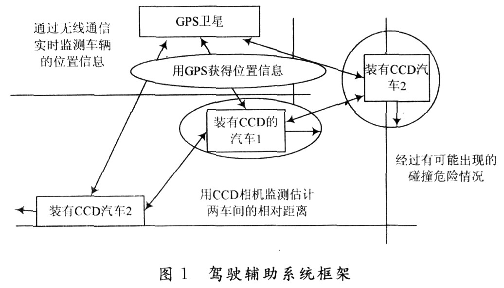
1.1 GPS module and CCD camera detection module The most likely place for collision accidents is in the corner of the car during driving. This is because the front window of the vehicle has a blind spot in the design process of the car, so that the driver does not have a corner when turning. It has a good vision, which makes it impossible to make a quick and clear judgment about the upcoming accident. In order to eliminate the problem of dead angle in the field of vision to the greatest extent, the driving assistance system uses GPS and CCD camera detection modules to obtain the driving data of the vehicle, including the vehicle's position, speed, and approach speed of the two vehicles.
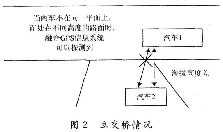
In order to reflect the distance and location information of the workshop, the road information in the geographic information system (GIS) is integrated into the GPS positioning data system to form a fusion GPS information system. In GIS, in order to truly reflect geographic entities, the recorded data not only contains the location, shape, size and attributes of the entities, but also records the interrelationships between the entities. This combination can meet the needs of this system well. Therefore, the position information transmitted by GPS satellites includes not only the longitude and latitude of the car, but also the altitude and the positional relationship between the vehicles, so that the geographic location of the car can be more accurately represented, avoiding the transmission of information between the two workshops The occurrence of an "overpass situation" (see Figure 2) will not cause the car to make a wrong judgment and cause unnecessary situations to occur.
The CCD cameras installed in the front and rear of the car are called "blind spot detectors", and their function is to observe the situation on both sides of the road in real time. Among them, the front CCD can detect the road condition after the turn in advance at the corner to determine whether there is a vehicle approaching; the rear CCD can see the driving situation of the vehicle behind and determine whether the vehicle affects the turning and overtaking of the vehicle.
Figure 3 shows a schematic block diagram of the process of using GPS and CCD cameras to determine the occurrence of a hazard and make a judgment operation based on the hazard. First, determine whether a vehicle is approaching the vehicle, and take the most dangerous approaching vehicle as the communication object; second, communicate through the Ad Hoc wireless network to obtain the driving information of the vehicle and the target vehicle, including speed, position, braking torque, etc. Based on this information, it is determined whether the driving condition of the target vehicle is normal. When the monitored information shows that the target vehicle is not operating normally, the two workshops transfer important information such as braking torque to each other, and according to the specific situation, obtain the distance information of the two workshops through the CCD camera in real time. Under certain circumstances, the two vehicle MCUs The controller will take active or automatic braking to avoid collision between the two cars, and the driver can also see this information through the monitoring screen in the car. Even when different dangerous situations occur during driving, the driving assistance system can make correct and accurate operations for different driving situations based on the information obtained from GPS and CCD cameras. 
1.2 Communication module The mobile Ad Hoc network is formed by the interaction of the wireless terminals loaded on the car without the support of other wired and wireless networks. Among them, each car is a mobile node in the mobile Ad Hoc network, and can freely join or leave the network. There is no network infrastructure in mobile Ad Hoc networks (such as base stations in cellular networks). All mobile nodes operate in a distributed manner and have a routing function. Using certain protocols, mobile nodes can discover and maintain routes for other nodes themselves. In addition to the data information transmission suitable for this driver assistance system, it also has some advantages that cellular mobile networks do not have:
(1) The network can be established at any time and used without other communication facilities, which greatly saves operating costs;
(2) It is not limited by the fixed topology, and it has strong fault tolerance and robustness. In some extremely harsh situations, even if some of the detected cars fail, the network can still operate normally.
The driving assistance system relies on the transfer of status information between vehicles to monitor the driving status, which can protect the driving safety, including adjusting the driving status to avoid vicious collisions. At present, the existing system can warn the driver of the advent of a dangerous situation, but cannot take preventive measures autonomously, and this system makes up for this defect. The information transmitted by the Ad Hoc network mainly includes two types:
(1) Regularly transmit the status information obtained by GPS and CCD cameras and some sensors in the car, such as: the vehicle's position, driving speed, braking torque, etc. According to research, these status information should be transmitted at a very high frequency, and each vehicle in the network is transmitted approximately 5 to 50 times per second.
(2) Warning information for dangerous situations. Unlike the information sent regularly above, these warning messages may come from the communication vehicles within the communication range, the nodes are far away, so multi-hop transmission is needed, so this information is only sent when a dangerous situation occurs.
Therefore, the system using the mobile Ad Hoc network transmission can implement real-time dynamic collection of vehicle driving conditions, which has the characteristics of low construction cost, short period and low maintenance cost, which is suitable for the current situation of intelligent transportation development in China. However, the mobile Ad Hoc network topology and physical layer protocol design, the processing of collected information and its prediction of future road conditions have yet to be resolved.
1.3 Control module When the vehicle information passed through the Ad Hoc network enters the vehicle controller, it will analyze and process the obtained data. If the result of the analysis is safe, no action is taken; when a warning appears in the result of the analysis, active preventive measures are taken, the process of which is shown in Figure 4.

The vehicle controller is the core of vehicle control. It judges the current state of the vehicle based on the input signal, and after certain control logic and control algorithm judgment analysis, determines the amount of current control signals sent to each subsystem. As shown in Figure 4, the speed signal represents the current vehicle demand for output driving torque. Similarly, the brake pedal signal represents the demand for vehicle braking torque. The automobile control strategy studied in this paper adopts the power auxiliary control strategy. The engine MCU determines the required fuel supply and injection timing according to the engine throttle signal sent by the assembly controller, combined with the current engine speed, so that the EFI engine outputs torque to the torque coupler through effective organization of combustion. The motor drive system determines the drive torque output of the motor based on the input motor throttle signal that characterizes the motor torque and the motor working mode signal.
The vehicle controller calculates the required mechanical braking torque value based on the driver's brake pedal and the current vehicle speed to obtain the braking command of the mechanical braking system. Compared with the original vehicle, the wheel braking force comes from the friction braking The braking system and the power transmission system that generates regenerative braking. The added regenerative braking function is realized by the hybrid power and transmission system. The regenerative braking force comes from the braking torque of the motor and is applied to the drive wheels through the transmission system. The moving energy is transmitted back to the motor through the transmission system. This improves the reliability of braking, thereby increasing the reliability and safety of the driver assistance system.
2 Principles of vehicle positioning To make the driving assistance system operate safely and reliably, the transmission of important driving information between cars is the key, and how to determine the car that communicates with the car is the basis. The judgment process is shown in Figure 5 and is divided into 4 steps.
(1) Suppose this is a vehicle flow model traveling from all directions (as shown in Figure 5 (a));
(2) The target vehicle traveling in the same direction as the own vehicle does not threaten the own vehicle, so it is removed from the candidate (as shown in Figure 5 (b));
(3) Vehicles with different destinations of their own vehicles are also removed from the candidates (shown in Figure 5 (c));
(4) Take the remaining vehicles as candidates for communication.

In the process of judging the driving direction of the vehicle, the signals transmitted by the GPS are analyzed, and the driving direction of the car is judged by the change of the vehicle's position; and inside the car, a gyro sensor can directly detect the direction of the car. When the travel directions displayed by the two messages are the same, the communication candidate vehicles are excluded according to the above removal rules; when the travel directions displayed by the two messages are different, they are reserved as communication candidate vehicles. The remaining candidate communication vehicles receive GPS satellite signals through a GPS receiver to find the latitude and longitude coordinates, speed, time and other information of the vehicle. From this information, parameters such as the distance between vehicles, the approaching speed between vehicles, etc. can be calculated, and the car with the closest distance and the fastest approaching speed is used as the communication object.
In order to improve the vehicle positioning accuracy, the system uses differential GPS technology. When the car travels to underground tunnels, high-rise buildings, highways and other coverings and cannot capture GPS satellite signals, the system can automatically import an autonomous navigation system. At this time, the speed of the car is detected by the vehicle speed sensor. Data processing, directly calculate the distance traveled, the distance and approach speed of the workshop from the speed and time. The vehicle position coordinate data and the direction of travel measured by GPS satellite navigation and autonomous navigation have certain errors with the actual route trajectory. In order to correct the errors of the two, they are integrated into the GIS system, using map matching technology and adding a map The matching circuit automatically corrects the error between the route traveled by the car and the road on the electronic map in real time. At this time, the map matching circuit is quickly processed by the finishing program of the micro processing unit to obtain the correctness of the car on the electronic map Location to indicate the correct driving route.
3 Conclusion The driving assistance system uses the GPS and CCD camera signals to monitor the status information of the vehicle in real time, and predicts the potential collision accidents in real time. When the judgment result shows that a collision accident is about to occur Through Ad Hoc network, wireless communication between vehicles is carried out, the driving parameters of the vehicle and the driving parameters of the communication vehicle are transferred to the microcontroller in the vehicle, so that the microcontroller issues operation instructions to remind the driver to do Out of control, when the situation is particularly urgent, you can directly control the vehicle appropriately. Since the driving assistance system does not require fixed monitoring equipment installed on both sides of the road, the system is very effective for future ITS.
ZhenHuan`s line of Battery Charger range in output power from 6 W to 100 W features high energy efficiency Level VI and reliability, with quick charging function for 18650 batteries and li-ion batteries, etc. Our desktop versions ac to dc power charger adopts constant voltage and constant current mode, all available with 2 colors LED indicator for charging status(Green and Red light). ZhenHuan`s power charger adapters solutions also includes class I and class II installations, equipped with IEC320-C8, IEC320-C6 and IEC320-C14 three standard AC inlet options.
Battery Charger Phones,Battery Charger Motorcycle,Battery Charger 42V,Best Battery Charger,Golf Car Battery Charger,Cell Phone Battery Charger
Shenzhenshi Zhenhuan Electronic Co Ltd , https://www.szzhpower.com