Overview:
In recent years, the problem of energy shortage has become increasingly prominent. People are worried about the exhaustion of energy, but the waste of energy is surprisingly large. For example, various discarded batteries, especially those used in remote-controlled toy cars, have been discarded even without using half of their energy, which not only causes waste of energy, but also causes environmental pollution. Therefore, it is urgent to develop a device for collecting energy of various used batteries.
This paper designs a power collection device with DC power converter as the core. This device can be used for people to charge mobile phones at any time during the journey, and can also be used for miner lighting. The charger delivers the power of a DC power source to a rechargeable battery of 3.6 V or higher. The system uses MC34063 and HT7750 to build the power supply circuit to charge the battery according to the input voltage. After the 89C51 single-chip microcomputer controls the AD0832 to detect the output voltage of the power supply, it can judge whether the battery is charged, and the detection time can be set according to the needs of the user. Set and display it through the digital tube. In order to improve the working efficiency of the single chip microcomputer, the single chip is in the dormant and working state for intermittent detection.
1. System Design Diagram The core of the power collection charger is a DC power converter, and the energy absorbed from the DC power source is transferred to the rechargeable battery. The power collection charger delivers the input power as much as possible to the device to be charged, so that the charging efficiency of the charger is as high as possible. The charger has low input voltage requirements and can absorb the energy in the DC power supply as much as possible, which is more energy efficient than the general charger. The system block diagram is shown in Figure 1. 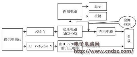
Figure 1 System block diagram According to the value of the voltage Ui, two DC power converters are used. When the voltage is 1.1 V< Ui <3.6 V, the Boost boost circuit composed of HT7750 is used. When the power supply is greater than 3.6 V, The circuit is realized by using a single chip microcomputer to control the integrated chip MC34063. The MC34063 operates from 3 to 40 V, so the power supply input voltage needs to be above 3 V to allow it to operate. The single-chip microcomputer can improve the efficiency by self-sleeping, and can also detect the voltage value to control the charging of the battery, and the digital tube displays the length of the detection time, which can be arbitrarily adjusted according to the requirements of the user. Such a circuit is intuitive, stable, and reliable, and in practical use, it can stably reach the required current value and voltage value under the condition of load. At the same time, the circuit is simple and easy to understand, easy to debug data, and has a high success rate.
(Please read the PDF for details)

The 60W Macbook Charger with MagSafe1 or Magsafe 2 Power Adapter has a magnetic DC connector, so if someone trips on it, the power cord disconnects harmlessly, keeping your MacBook Air safe. It also helps prevent the cable from fraying or weakening over time. Additionally, the magnetic DC helps guide the plug into the system for a quick and safe connection.
60W Apple charger usb c,60w charger macbook air,macbook 60w charger
Shenzhen Waweis Technology Co., Ltd. , https://www.waweisasdapter.com