Design of reversing radar based on MSP430F2274 microcontroller
With the improvement of people's requirements for intelligent driving assistance systems and the development of networked automotive electronic systems, the new reversing radar should be able to continuously measure and display the distance of obstacles, and have a communication function to send data to the car bus. . In the past, the design of reversing radar used many components and its functions were relatively simple. The reversing radar based on the new high-performance ultra-low power microcontroller MSP430F2274 introduced in this article can make up for the shortcomings of previous products.
Overall system design
The system uses the principle of ultrasonic ranging. Ultrasonic ranging instruments are generally composed of three parts: transmitter, receiver and signal processor. When working, the ultrasonic transmitter sends out ultrasonic pulses, the ultrasonic receiver receives the reflected wave reflected back from the obstacle, accurately measures the time from the transmission of the ultrasonic wave to the reflection of the obstacle, and the obstacle can be calculated according to the propagation speed of the ultrasonic wave distance. As a non-contact detection method, ultrasonic waves have the characteristics of low air propagation attenuation, strong reflection ability and strong penetration. Ultrasonic ranging has the advantages of not being affected by light and rain, snow and fog in a short range, simple structure, convenient production and low cost. High-performance single-chip microcomputer combined with ultrasonic ranging can realize a powerful and convenient parking radar. TI's 16-bit microcontroller MSP430F2274 has extremely low power consumption and abundant on-chip resources. At the same time, JTAG interface technology can be used to easily program on-chip flash memory and software upgrades. It is very suitable as a microcontroller for reversing radar systems. The block diagram of the reversing radar system is shown in Figure 1.
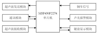
Figure 1 Block diagram of reversing radar system
Hardware system design
The system takes the MSP430F2274 microcontroller as the core, and the peripheral circuit is composed of five parts: an ultrasonic transmitting circuit, an ultrasonic receiving circuit, an acousto-optic alarm circuit, a communication interface circuit, and a keyboard liquid crystal display circuit.
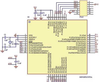
Figure 2 Main control circuit diagram of reversing radar system
The main control circuit diagram of the system is shown as in Fig. 2. The MSP430F2274 selected in this system has 32Kb flash memory and 1Kb RAM, so there is no need to expand the memory. The external 32.768kHz crystal oscillator is used as the clock source for the Basic-TImer in the CPU off state, and it is also used as the system's car clock.
The circuit of the ultrasonic transmission module is shown in Figure 3, which is composed of ultrasonic generation and transmission. There are two methods for generating ultrasonic waves: hardware generation method and software generation method. The commonly used hardware generation method often adopts the following scheme: the ultrasonic wave is generated by the oscillator composed of the CD4011, and the ultrasonic transducer is driven by the boost conversion to be emitted, and the start and stop of the oscillator are controlled by the single-chip microcomputer. This design uses the software generation method, because the software generation method can not only reduce the complexity of the hardware and reduce the cost of the system, but also has the advantages of strong flexibility, easy implementation, and good stability. This system uses the timer function of the MSP430F2274 microcontroller to generate a stable PWM (40Hz) pulse wave, and outputs it to the ultrasonic transmission part through the I / O port P2.3. In the ultrasonic transmission circuit, the CD4049 includes a total of 6 NOT gates. Only three lines are used in Fig. 3. To prevent interference or electrostatic breakdown, the entire CD4049 is damaged. Get up for grounding. When a series of fixed-frequency pulses are output from the control terminal, a positive frequency and a reverse voltage of fixed frequency are applied to the piezoelectric ceramic ultrasonic transmitting transducer UCM-40-T to emit high-power ultrasonic waves, and the resulting waveform is better than other The effect is more ideal.
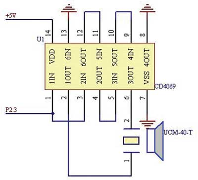
Figure 3 Ultrasonic transmission module of reversing radar
The ultrasonic receiving circuit is shown in Figure 4. This is a difficulty in the design and debugging of this system. Piezoceramic ultrasonic receiver UCM-40-R converts the reflected ultrasonic wave into a voltage signal of 40kHz millivolt level, which needs to be amplified and processed before it can be used to trigger the interruption of the microcontroller. On the one hand, the output signal of the sensor is weak. Due to different reflection conditions, the range of magnification required is about 100 to 5000. On the other hand, the output impedance of the sensor is large, and a multi-stage amplifier circuit with high input impedance is required, and the high input impedance is easy to receive interference signals. . Two schemes are usually adopted: one is to use an operational amplifier to form a multi-level frequency selective amplifier circuit; the other is to use a dedicated integrated preamplifier. The first scheme is prone to self-oscillation, and it is difficult to debug the circuit if the receiving circuit can achieve good sensitivity and anti-interference effect. This system uses a dedicated integrated circuit preamplifier CX20106, which consists of preamplifier, limiting amplifier, band-pass filter, detector, integrator, and integral circuit. The preamplifier has an automatic gain control function, which can ensure that the amplifier has a higher gain when the ultrasonic sensor receives a remote reflection signal and outputs a weak voltage, and the amplifier will not be overloaded when the close-range input signal is strong. Adjust the external resistor R3 of pin 5 of the chip and set the center frequency of its filter to 40 kHz, which achieves a very good effect. When receiving a signal that matches the center frequency of the filter, its output pin 7 outputs a low level, and the output pin 7 is directly connected to P2.2 of the MSP430F2274 to trigger an interrupt.
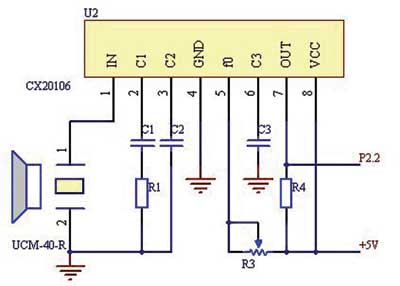
Figure 4 Ultrasonic receiving module of reversing radar

Figure 5 Reversing radar sound and light alarm circuit diagram
The alarm module uses a simple sound and light alarm circuit, as shown in Figure 5. First set a critical value. When the distance between the rear of the vehicle and the obstacle is less than the set minimum distance, the red indicator light flashes and the green indicator light turns off. The MCU sends PWM pulses to its ports. As the distance decreases, the frequency of the flash and buzzer is increased by controlling the duty cycle of the PWM pulses to remind the driver.

Figure 6 Circuit diagram of the parking radar communication interface
The communication interface circuit is shown in Figure 6. Using Maxim's MAX3232 chip, the peripheral circuit is very simple, requiring only five 0.1μF capacitors. This circuit isolates and converts the output signal of the serial port of the single-chip microcomputer into an RS-232 signal and sends it to the bus of the car. At the same time, it can also realize the communication between the system and the computer.
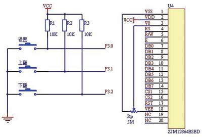
Figure 7 Circuit diagram of reversing radar keyboard display
The keyboard and display circuit are shown in Figure 7, which consists of a keyboard and a liquid crystal display. The keyboard uses independent keys, there are 3 keys, a set key, an up key, a down key. Various parameters such as alarm value, working mode and clock can be set. The liquid crystal display circuit uses ZJM12864BSBD, a low-power dot-matrix LCD with a display format of 128 dots (columns) × 64 dots (rows). It has multi-function instructions and is easy to use. It can display the clock, distance, and alarm prompts in real time. Information, convenient and intuitive.
System software design
The software adopts a modular design. The program is composed of a main program, a distance measuring subprogram, a keyboard display subprogram, a clock display subprogram, and other modules. During the debugging process, each of the functional modules and subprograms is debugged one by one. After completing the specified functions, carry out comprehensive debugging. The software flow of the system is shown in Figure 8.

Figure 8 System software flow chart
When the ultrasonic transmitter circuit sends out ultrasonic waves, the counter starts to count. When encountering obstacles, the feedback signal is received by the ultrasonic receiver. After being processed by the CX20106 receiving circuit, a low pulse is generated. This signal is sent to the microcontroller to generate an interrupt, and the distance measurement subroutine is called. Calculate the measured distance, call the display subroutine, and display the distance and alarm on the LCD according to different measured values. When the distance is greater than 2m, display "safe" and measure the distance, continue to measure; when the distance is less than 1m, display "danger" and measure the distance, the buzzer is driven by P1.2 alarm; when the distance is less than 2m and greater than 1m, "Attention" and the measured distance are displayed. In order to enhance the anti-interference ability, the system continuously transmits ultrasonic measurement three times, removing the maximum and minimum values ​​from it, and taking the middle value to calculate the precise distance. In this way, about three data can be measured per second, which can still meet the real-time requirements.
Conclusion
The reversing radar uses a high-performance MSP430F2274 single-chip microcomputer, and makes full use of its on-chip resources to make the system rich in functions, reduce the use of peripheral chips, and improve system reliability. The reversing radar is used in a car. When the driver reversing, the distance of the obstacle from the car can be known at a glance on the LCD screen, which overcomes the shortcomings of the small rearview mirror and the narrow field of view, and eliminates the hidden accidents caused by reversing.
modern led crystal wall lamp, main material is stainless steel and Top K9 crystals. The light source is LED SMD . There are many different patterns and designs for customer to choose.
Wall lamp lighting should not be too large, so more artistic appeal, the choice of wall lamp shade should be based on wall color. In a large area of the same color background wall cloth, dotted with a prominent wall lamp, giving a sense of fresh and fresh.


Modern Crystal Wall Lamp,Crystal Wall Lights,Modern Lighting,Stylish Wall Lights
Zhongshan Laidi Lighting Co.,LTD , http://www.idealightgroup.com