1, main memory overview
(1) Two important technical indicators of main memory
â—Ž read and write speed: often measured by the storage period, which is the time interval necessary to continuously initiate two independent memory operations (such as read operations).
â—Ž Storage capacity: Usually measured by the number of bytes or words constituting the memory.
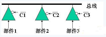
(2) Connection of main memory to CPU and peripheral devices
Is connected through the address bus, data bus, control bus, see the following figure
Main memory and CPU connection
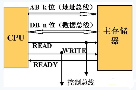
â—Ž The address bus is used to select a memory cell of the main memory. If the bit number of the address bus is k, the maximum addressable space is 2k. If k=20, you can access 1MB of storage unit.
â—Ž Data bus is used to transfer data between various functional components of the computer.
â—Ž The control bus is used to indicate the duty cycle of the bus and the time at which the input/output is completed.
(3) Main memory classification
â—Ž Long and short points according to information storage: ROM and RAM
â—Ž According to the production process: static memory and dynamic memory
Static Memory (SRAM): Fast read/write speed, high production cost, and mostly used for small-capacity cache memories.
Dynamic Memory (DRAM): slower read/write speed, high integration, low production cost, and mostly used for main memory with large capacity.
The main performance comparison between static memory and dynamic memory is as follows:
Comparison of static and dynamic memory chip characteristics
SRAM DRAM
Store information trigger capacitor
Destructive readout
Need to refresh, don't need
Send the row address and send it twice at the same time
Running fast
Low integration
Calorific value
Storage cost
Periodic refresh of dynamic memory: When no read/write operation is performed, each unit of the DRAM memory is in a power-off state. Due to the existence of leakage, the charge stored in the capacitor CS will slowly leak out, and this must be supplemented periodically. It is called a refresh operation.
2. Memory principle and read and write process of dynamic memory
(1) The composition of dynamic memory: a single MOS tube is used to store one bit of binary information. The information is stored in the parasitic capacitance CS of the source of the MOS transistor.
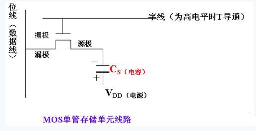
â—Ž When writing data: The word line is high level and T is turned on.
When writing "1", the bit line (data line) is low, and VDD (power) will charge the capacitor.
When “0†is written, the bit line (data line) is high. If the capacitor stores a charge, it will cause the capacitor to discharge, indicating that “0†is stored.
â—Ž When reading data: first make the bit line (data line) high. When the word line is high, T turns on. If the capacitor originally stores charge (is "1"), the capacitor will discharge. This will cause the data line potential to go from high to low; if the capacitor does not store charge (is "0"), the data line potential will not change. By detecting the change in potential on the data line, it is possible to distinguish whether the read data is 1 or 0.
note
A read operation causes the charge stored in the capacitor to be lost, and is therefore a destructive read. In order to maintain the original memory content, a write operation must be followed immediately after the read operation, which is called a precharge delay.
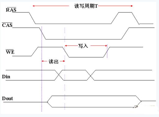
2 Provide an address to the memory unit of the dynamic memory, which is the first line address and then the column address. The reason is that the dynamic memory must be refreshed periodically (such as 2ms). The refresh is not word-by-word processing, but each time a row is refreshed, that is, the energy of all the memory cells connected to the same row is supplemented once.
3 The readout signal on the bit line of the dynamic memory is very small, and must be connected to the sense amplifier, usually implemented by a flip-flop line.
4 The row address and column address latches inside the memory chip accept row and column addresses in succession.
The timing relationship of 5RAS, CAS, WE, Din, Dout is as follows:
3. The composition and design of the internal memory of the teaching computer
(1) Storage principle of static memory and internal structure of chip (P207)
(2) The composition and design of the memory in the teaching computer
â—Ž Address bus: It is recorded as AB15~AB0, which is driven by the address register AR. The address register AR only receives the information output by the ALU.
â—Ž Control bus: The signal of the control bus is given by the decoder 74LS139. The function is to indicate the type of bus cycle:
※ Memory write cycle is marked with MMW signal
※ Memory read cycle is marked with MMR signal
※ Peripheral (interface) write cycle is marked with IOW signal
※ Peripheral (interface) read cycle is marked with IOR signal
※ Memory is marked with MMREQ signal for work
※ Peripherals are marked with IOREQ signal at work
※Write control cycle is marked with SWA signal
â—Ž Data bus: divided into two parts: internal data bus IB and external data bus DB. Mainly complete the data transfer between the various functional components of the computer.
The core technology of the design bus is to ensure that only one set of data can be sent to the bus at any time, while allowing one or more components to simultaneously accept information on the bus. The circuit used is typically a three-state gate.
â—ŽSystem clock and timing: The teaching machine crystal oscillator is 1.8432MHz. After dividing by 3, the 614.4KHz clock is used as the system master clock to make the CPU, memory and IO run synchronously.

Some registers inside the CPU complete the acceptance of data with the rising edge at the end of the clock, while the general-purpose registers are received with low level. In memory or I/O read and write operations, each bus cycle consists of two clocks. The first clock, called the address time, is used to transfer the address. The second clock, called the data time, is used to read and write data.
â—Ž static memory word slot expansion:
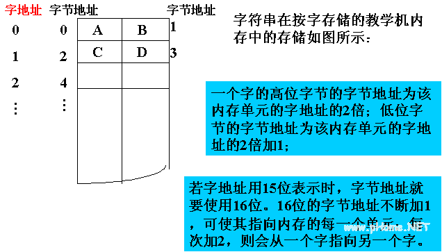
The internal memory of the teaching computer is implemented by a static memory chip, which is composed of a 2K word ROM area and a 2K word RAM area. The memory word is 16 bits long and is addressed by word.
The ROM is extended by the 74LS2716 read-only memory ROM (2048 memory cells per chip, each bit is 8-bit binary bit). Address allocation: 0 ~ 2047
The RAM is extended by the 74LS6116 random access RAM (2048 memory cells per block, 8 bits per cell). Address allocation: 2048 ~ 4095
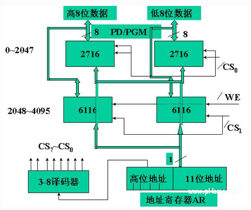
Static memory word, bit extension
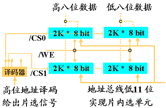
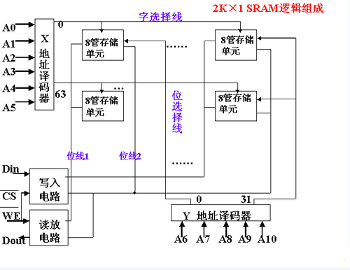
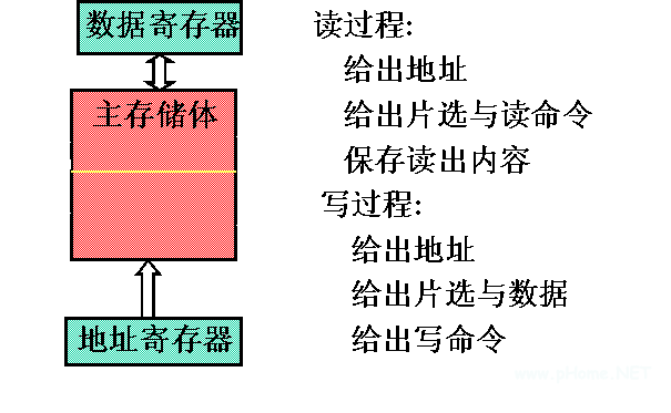
Main memory read and write process
Static memory address assignment:
To access 2048 memory locations, the 11-bit address is used to send the lower 11-bit address of the address bus to the address pin of each memory chip; the upper bits of the address bus are decoded, and the decoded signal is sent to each memory chip. /CS pin,
â—Ž Implement byte-by-byte read and write in word-addressable memory systems
4, main memory implementation and several techniques in the application
(1) Fast read and write technology of dynamic memory
â—Ž fast page work technology (fast read and write technology of dynamic memory)
When reading and writing the data of the same line of dynamic memory, the row address will remain unchanged after being locked for the first time. When reading and writing data in multiple columns of the row, only the column address can be latched, and the latch is omitted. The time of the row address speeds up the read and write speed of the main memory.
â—ŽEDO (Extended Data Out) technology
In the fast page type working technology, the data latching line of the data output part is added, and the effective holding time of the output data is prolonged, so that the address signal is changed, and the correct reading data can still be obtained, and the address feeding time can be further shortened. Speed ​​up the read and write speed of the main memory.
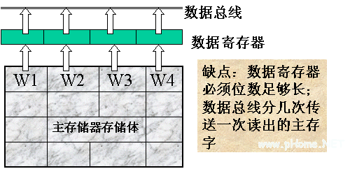
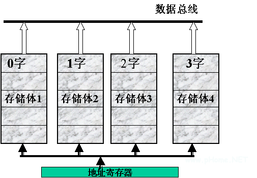
(2) Parallel read and write technology of main memory
It refers to the technique used to read multiple main memory words in one duty cycle (or longer) of the main memory.
Solution 1: An integrated multi-word structure, that is, increasing the data bits included in each main memory unit to store several main memory words at the same time, and reading several main memory words at the same time for each read operation.
Scheme 2: Multi-body cross-addressing technology, the main memory is divided into several main body that can be read and written independently, and the word length is a main memory word, and each memory is read and written separately; Run to provide higher read and write speeds than a single bank.
There are two ways to read and write:
â—Ž Start all main memory read or write at the same read and write cycle.
â—Ž Let the main memory read or write sequentially, that is, each memory word read out in sequence can be sequentially transferred through the data bus without setting a special data buffer register. Secondly, the method of cross-addressing is adopted. Several memory words of consecutive addresses are sequentially allocated in different banks, because according to the local characteristics of the program running, the probability of reading and writing adjacent main words in a short time is greater.

(3) Memory support for group data transfer
The so-called group data transfer is that after the address bus transmits the address once, it can continuously transmit a plurality of data on the data bus. Originally, it takes two clock cycles to transmit data once: first send an address first, followed by a data transfer, that is, to transmit N data, it is necessary to use 2N bus clock cycles, and the group data transmission mode only uses N+1. Bus cycle time.
To achieve a group data transfer mode, not only the CPU must support this mode of operation, but also the main memory can provide a high enough data read and write speed, which is often achieved by means of a multi-body structure of the main memory and EDO support of the dynamic memory.
Carbide Taps
OPT Diamond Cutting Tools Co., Ltd are a professional manufacture in producing Cutter Taps ,Thread Forming Taps,pipe taps etc . We offer a complete range of taps in carbide, CPM and HSS-E.For carbide taps, we provied regular stock, and we also provide customization for your designs and logo. It is important to choose a professinonal manufacture to work with you, in order to communicate every details in the design. Our reputation has been built on quality, design and service – all at a competitive price. No matter you are a agent buyer or a factory source for self-use, we will be your most trusted partner.
Carbide taps is used to cut a screw thread in material with a pilot hole, threading is a process of both external and internal machining of threads into a workpiece. A number of angles and measurements defines the thread of the screws and bolts. All are of importance:
The lead is the distance through which a screw advances with one turn in the direction of the shaft. There are single lead threads and multiple lead threads. Multiple lead threads are able to feed faster with fewer revolutions.
The pitch is the distance between the corresponding threads in the axial direction.
The effective diameter is the midway point between the crest and root. In other words, the point where the internal thread and external thread overlap when screws are meshed together. The effective diameter is, along with pitch, one of the most important dimensions in threads.
According to the application, there are several kinds of taps: Machine and hand taps, spiral flute taps, spiral pointed taps, thread forming taps, and Pipe taps and thread milling cutter.
1. Machine and hand taps
The very standard tap, mostly are the Straight flute tap. Typically, tap is constituted by a working portion and a shank portion. The working portion is divided into a cutting portion and a calibration section, the cutting portion having a cutting bevel, responsible for cutting work. The calibration section is used to calibrate the size and the shape of the thread.
2. Spiral flute taps:
The spiral flutes have high cutting performance, eject chips smoothly, leave no chips in the hole bottom, suitable for tapping sticky materials. The chip-hold groove of Spiral fluted tap is spiral. According to the application, they are divided into two kinds: Left spiral flute tap and right spiral flute tap. Left Spiral flute tap tapping the chip to the bottom, suitable for through hole. Right spiral flute tap tapping scraps discharge upwards, so its suitable for blind holes.
3.Spiral pointed taps:
Suitable for through-hole and deep thread, have high strength, long life, fast cutting, dimensional stability, explicit tooth pattern (especially fine tooth). It opens chute in the side of the cutting edge of the straight groove, to form an angle, the chips are discharged forward when threading, suitable for through-hole processing. Relatively large core size design, good strength, can withstand greater cutting force. It is suitable for processing of non-ferrous metals and stainless steel and black metallic.
4. Thread forming taps:
These taps make threads by deforming the materials and do not produce chips. They are suitable for the blind holes of rather soft material or non-ferrous metals. The internally extruded and threaded metal has fibers which are continuous and has high tensile strength and shear strength, and has good surface roughness too.
5. Pipe taps
The pipe taps are used for mechanical joints purpose which is cutting the pipe fitting threads. There are two kinds of types, taps for parallel threads and taps for taper threads. The parallel threads are used for mechanical joints. The taper threads are used for pressure type joints such as water pipes and gas pipes.
6. Thread Milling cutter:
The thread milling cutter is a new developed processing tool in recent years. Its the combination of the milling cutter and the tap, using milling for machining the thread, so we call it the thread milling cutter. It is suitable for processing the large aperture work piece, avoid the disadvantage of high cost for large size Taps.
We are specialize in manufacturing PCD diamond tools and Carbide tools. Our major product include PCD Inserts , PCD Reamers , PCD End Mills , PCD Taps, Carbide Inserts, Carbide Drills, Carbide Reams, Taps etc.. Premium quality of raw material is used in the production and strict examination during processing with advanced equipment. Our best selling of cutting tools include PCD Inserts, PCD End Mill, PCD Reamer, Carbide Taps, Carbide End Mills, Special Form Cutter and many more.
Target of our OPT cutting tools is always to improve your productivity and lower total cost. If you encounter problems such as high-speed, high precision requirements, low tool life and so on in the processing, you may contact us to recommend appropriate design for you, we can provide customization per your drawing. We looking forward to make a long business relationship with you.
PRODUCT DETAIL:


PRODUCTING PROGRESS:

PAYMENT AND DELIVERY:

PRODUCT EQUIPMENT :
+
ABOUT US :
We are specialize in manufacturing PCD diamond tools and Carbide tools. Our major product inclulde PCD inserts, PCD Reamers, PCD End Mills, PCD Taps, Cabide Inserts,Carbide Drills, Carbide Reams, Taps etc.,
We also offered customized cutting tools per drawings, and provide package according to customer requirements. We manufacture a series range of cutting tools for machining of Cast iron, Aluminium alloy and Non-Ferros metal, it is widely used in all major sectors like Automobiles, Engineering, Aerospace, Aviation and 3C industry. Premium quality of raw material is used in the production and strict examination during processing with advanced equipment, so our client are satisfied with our reliable quality and on-time delivery.
Our best selling of cutting tools include PCD Inserts, PCD End Mill, PCD Ball Nose Mill, PCD Reamer, Carbide Taps, Carbide End Mill, Special Form Cutter and many more. For these years we have been made a large forward in the technologies of manufacturing cutting tools. With high quality on performance and price, our product sells well both on domestic and overseas market. And we will always focus on the quality and best service, to make long business relationship.

quanlity control:
We have dedicated team of quality control and precise equipment to keep good and stable performance for our products and processing services.

Carbide Taps,Thread Tap,Solid Carbide Taps,Pipe Tap Set
OPT Cutting Tools Co., Ltd. , https://www.optdiamondtoolss.com