LDPC code
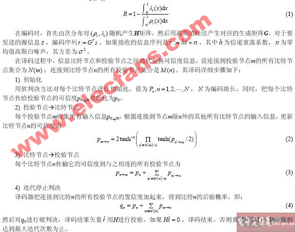
The LDPC code is a linear block parity check code, which uses Belief PropagaTIon (BP) iterative decoding algorithm based on factor graph for decoding. Its performance is close to Turbo codes, and irregular LDPC codes even exceed Turbo code performance. Because the Turbo code adopts the puncturing method to adjust the code rate, a low-weight code word may be generated, resulting in a flattened bit error rate performance curve at a high signal-to-noise ratio [4]. The distance between the code words of the LDPC code will increase with the increase of the code length, so that its decoding errors can be detected. This feature has practical value, such as error-free transmission under the ARQ system.
The check matrix H of the LDPC code is a sparse matrix. For GF (2), the number of '1's in the rows and columns of H represents the degree of sub-distribution of each information bit and parity bit, respectively. "Row times" means the number of information bits participating in each test equation; "Column times" means the number of times each information bit participates in the test. The greater the "column order", the performance of the LDPC code can be arbitrarily close to the Shannon limit. However, if the "column order" is too large, the number of "circles" during decoding will increase sharply, which will seriously deteriorate the decoding performance. Generally, the "column order" is greater than 2. In addition, when the "column order" is equal to each column of H, it is called a regular LDPC code, otherwise it is an irregular LDPC code. Irregular LDPC codes have better performance than regular LDPC codes.
Assuming that the secondary distribution pair of LDPC codes is (,) iiÏλ, the code rate of LDPC [5]:
Analysis of code modulation performance of concatenated LDPC codes and CCK
Surface-mount technology (SMT) is a method for producing electronic circuits in which the components are mounted or placed directly onto the surface of printed circuit boards (PCBs). An electronic device so made is called a surface-mount device (SMD). In industry, it has largely replaced the through-hole technology construction method of fitting components with wire leads into holes in the Circuit Board. Both technologies can be used on the same board, with the through-hole technology used for components not suitable for surface mounting such as large transformers and heat-sinked power semiconductors.
By employing SMT, the production process speeds up, but the risk of defects also increase due to the components miniaturization and denser packing of boards. In those conditions, detection of failures has become critical for any SMT manufacturing process.[1]
An SMT component is usually smaller than its through-hole counterpart because it has either smaller leads or no leads at all. It may have short pins or leads of various styles, flat contacts, a matrix of solder balls (BGAs), or terminations on the body of the component.

Surface Mount Technology,Surface Mount,Surface Mount Assembly,Surface Mounting Technology
Orilind Limited Company , https://www.orilind.com