To detect medium and small power transistors, you can use several methods based on their type and pin configuration. One common approach is to measure the inter-electrode resistance. Set your multimeter to R×100 or R×1K mode and test all six possible connections between the red and black probes. The emitter-base and collector-base junctions should show relatively low resistance, while the other four combinations will have high resistance, typically ranging from hundreds of kilohms to infinity. However, silicon transistors generally have higher inter-electrode resistance compared to those made of tantalum.
Another important parameter is the penetration current (ICEO), which is approximately equal to the product of the transistor's current gain (β) and the reverse collector current (ICBO). ICBO increases with temperature, leading to a rise in ICEO, which affects the stability of the transistor. Therefore, it’s better to use transistors with a low ICEO for stable performance. You can estimate ICEO indirectly by measuring the resistance between the collector and emitter using a multimeter. For PNP transistors, connect the black probe to the emitter and the red probe to the collector; for NPN, reverse this. A higher resistance indicates a lower ICEO, and vice versa. Medium and small power silicon transistors should ideally show resistances in the range of hundreds of kilohms or more, while tantalum transistors may show lower values. If the resistance is low or the meter needle fluctuates, it suggests a high ICEO and unstable performance.
To measure the amplification capability (β), some multimeters have an hFE setting with a dedicated socket. Turn the function switch to the appropriate position, short the leads, adjust the zero, then place the transistor in the socket and read the β value from the hFE scale. Some manufacturers also mark the β value on the top of the transistor using color codes, though these may vary between brands.
To identify the base, emitter, and collector, start by testing each pair of electrodes. When one lead is connected to a terminal and the other touches the other two, the one showing low resistance is the base. The polarity of the multimeter leads helps determine if it’s PNP or NPN. Once the base is identified, the collector and emitter can be distinguished by measuring resistance between the base and the other two terminals. For a PNP transistor, the terminal with lower resistance when the black probe is used is the collector, and the one with higher resistance is the emitter.
High-frequency transistors have a cutoff frequency above 3 MHz, while low-frequency ones are below that. They are not interchangeable under normal conditions. In practical applications, especially when transistors are soldered onto a PCB, it’s common to measure DC voltages at each pin to assess functionality and determine if the transistor is working properly.
For high-power transistors, the detection method is similar, but due to larger PN junctions and higher currents, the multimeter is usually set to R×10 or R×1 instead of R×1K to avoid false readings that might suggest a short circuit. This ensures more accurate results when testing high-current devices.
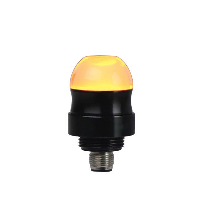
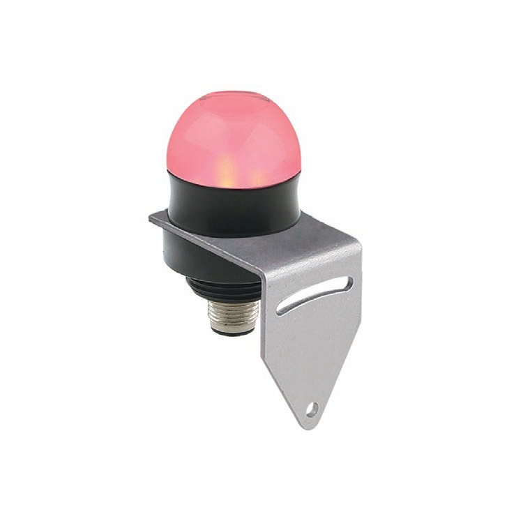
SVLEC provide multi-functional signal indicator light , tower light , Cabinet lamp , Strip led lamp with M12 socket . , Signal tower series based on LED light source design , long service life , no maintenance . The model is rich , unique , firm and durable , it is assembled by the factory and has a variety of installation Accessories . Various models can provide customers with customized solutions , including AC, DC power selection , three alarm output options , standard or high brightness selection, and fast connector or cable selection.


indicator light,tower light,Cabinet lamp,Strip led lamp,3 color indicator
Kunshan SVL Electric Co.,Ltd , https://www.svlelectric.com