To address the challenge of detecting micro-scale capacitance variations in capacitive sensors, a digital and universal detection interface has been proposed. This approach is based on the "excitation-detection" principle, where a direct measurement of small capacitances is achieved by analyzing both amplitude and phase information. A Direct Digital Synthesizer (DDS) is used to generate the excitation signal, while a Discrete Fourier Transform (DFT) is applied to separate the amplitude and phase components of the response. This enables accurate determination of capacitance changes.
The design was tailored for proximity capacitive sensors, and a dedicated hardware circuit was developed to validate its performance. Experimental results demonstrated that the system achieves a detection accuracy exceeding 95%. It is capable of detecting capacitance variations as small as 0.1 pF, which makes it suitable for high-precision applications. The simplicity of the design also ensures strong portability and ease of integration into various systems.
1. Introduction
Capacitive sensors are widely utilized due to their compact size, low power consumption, and high sensitivity. They are commonly employed in non-electrical measurements such as acceleration, angular velocity, and pressure. However, designing an effective detection interface for capacitive sensors remains a complex task. Traditional approaches often rely on analog components, leading to larger system sizes and introducing issues like temperature drift and nonlinearity. In this paper, we present a digital and universal detection interface that simplifies the design, reduces errors, and enhances overall accuracy by leveraging both amplitude and phase relationships.
2. Capacitive Sensor Model
A capacitive sensor converts physical quantities into changes in capacitance. It is extensively used in measuring parameters like acceleration, angular velocity, and pressure. To enhance signal strength, the variable pitch method is frequently applied to improve sensitivity.
For example, a capacitive pressure sensor typically consists of two plates, A1 and A2, with A1 being fixed and A2 movable. A3, the sensitive diaphragm, responds to external pressure, causing A2 to move closer to A1. This change in distance alters the capacitance between the plates, which can then be measured to determine the corresponding pressure value.
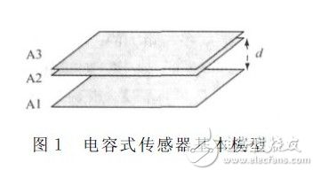
When no pressure is applied, the initial capacitance is given by:

where ε is the dielectric constant, A is the overlapping area, and d₀ is the initial separation between the plates.
When an external pressure is applied, the spacing decreases, resulting in an increase in capacitance:
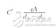
where dx represents the change in spacing.
3. Direct Interface Detection Principle
Traditional capacitive sensor interfaces include continuous-time readout methods like charge amplifiers and transimpedance amplifiers, as well as discrete-time methods such as switched capacitor circuits. These approaches convert capacitance into voltage or current, making them indirect and less ideal for system integration. Instead, capacitors modulate both the amplitude and phase of the electrical signal, offering a new opportunity for more accurate and integrated detection solutions.
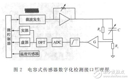
Figure 2 illustrates the interface design, where C represents the capacitive sensor, and R1 and R2 are auxiliary resistors used to match the sensor’s capacitance. The microcontroller generates a single-frequency sinusoidal carrier using DDS, adjusts the amplitude, and sends it to the sensor. The output is compared with the auxiliary resistor, amplified, filtered, and then transformed via DFT to extract real and imaginary components for further processing.
Assuming the carrier is VDDS = Aâ‚€sin(2Ï€ft), the excitation voltage becomes Vdrive = Aâ‚Aâ‚€sin(2Ï€ft). The detection voltage is given by:
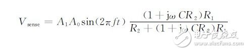
After Analog-to-Digital conversion, the detected voltage allows us to calculate the complex impedance of the capacitance:
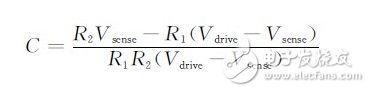
where Vdrive and Vsense are complex variables. Since the input signal is sinusoidal, the amplitude and phase information are stored in the real and imaginary parts, respectively. Applying DFT to Vsense provides the necessary data to detect capacitance changes accurately.
4. Actual Circuit Design for Detection Interface
Given the wide range of capacitive sensors and varying capacitance values, the choice of components must be tailored to specific measurement ranges. A proximity capacitive sensor, for instance, uses three plates: one movable plate representing the object under test (such as a finger), and two fixed plates. One block is excited with a constant sinusoidal voltage, while the other is grounded. When the object approaches, the capacitance increases, and if it exceeds a certain threshold, the system detects the presence of the object.
At the heart of this sensor is the ability to detect minute changes in capacitance. Based on the principles discussed, a practical circuit was designed and implemented to demonstrate the effectiveness of the proposed detection method.
Overhead Line Fitting,Short Insulator Pin For Insulator Supporting,Spindle For Insulator,Ceramic Pin Insulator
Shahe Yipeng Import and Export trading Co., LTD , https://www.yppolelinehardware.com