To address the challenge of detecting micro-level capacitance variations in capacitive sensors, a digital and universal detection interface scheme has been proposed. The principle of direct micro-capacitance measurement based on the "excitation-detection" method is analyzed in detail. A carrier signal is generated using Direct Digital Synthesis (DDS), and the amplitude and phase of the measured signal are separated through Discrete Fourier Transform (DFT) to determine the capacitance change accurately. A specific hardware circuit was designed for verification, tailored for the requirements of proximity capacitive sensors. Experimental results show that the detection accuracy exceeds 95%, with the ability to detect micro-variable capacitance as small as 0.1 pF. The design is simple, efficient, and highly portable, making it suitable for various applications.
1. Introduction
Capacitive sensors are widely used in non-electrical measurements such as acceleration, angular velocity, and pressure due to their advantages of compact size, low power consumption, and high sensitivity. However, unlike resistive sensors, the design of a capacitive sensor's detection interface is complex and challenging. Traditional methods often rely on analog components for amplification and sampling, which not only increases system size but also introduces errors related to temperature and nonlinearity. This paper presents a universal digital detection interface for capacitive sensors. By analyzing the relationship between amplitude and phase comprehensively, the design is simplified, errors are minimized, and detection accuracy is significantly improved.
2. Capacitive Sensor Model
A capacitive sensor converts the physical quantity being measured into a change in capacitance. It is commonly used in the measurement of parameters like acceleration, angular velocity, and pressure. To enhance the signal output, variable pitch techniques are frequently employed to improve sensitivity.
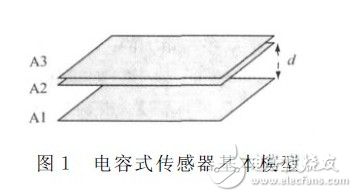
As an example, consider a capacitive pressure sensor. Its basic structure is illustrated in Figure 1. A1 and A2 represent two capacitor plates, where A1 is fixed and A2 is movable. A3 is a sensitive diaphragm that responds to changes in air pressure. The distance between A1 and A2 is denoted as d. When an external pressure is applied, A3 moves A2 closer to A1, changing the capacitance between them. Detecting this change allows the corresponding pressure value to be determined.
When no pressure is applied, the initial capacitance of the sensor is given by:

Where ε is the dielectric constant, A is the overlapping area between the plates, and d₀ is the initial spacing between them.
When an external pressure is applied, A2 moves closer to A1, reducing the distance dâ‚€. The resulting capacitance becomes:
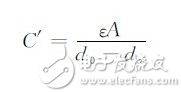
Here, dx represents the change in spacing between the plates.
3. Direct Interface Detection Principle
Common capacitive sensor interfaces include continuous-time readout circuits such as charge amplifiers and transimpedance amplifiers, as well as discrete-time readout circuits like switched capacitor types. These typically convert the measured capacitance into voltage or current, which is essentially an indirect detection method that hinders system integration. As a non-resistive component, a capacitor modulates both the amplitude and phase of its electrical signal. Leveraging this relationship, a detection scheme that simultaneously measures both amplitude and phase can be developed.
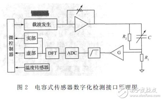
Figure 2 illustrates the interface design. C represents the capacitive sensor, while R1 and R2 are auxiliary resistors selected and matched according to the capacitance of the sensor under test.
The microcontroller generates a single-frequency sinusoidal carrier using DDS. After amplitude adjustment, it is sent to the capacitive sensor. The waveform is then compared with the auxiliary resistor, amplified, filtered, and converted via AD. The resulting data undergoes DFT to separate the real and imaginary parts, which are then processed by the microcontroller for further calculations and linearization.
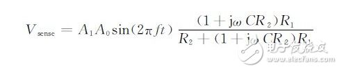
Assuming the carrier signal is VDDS = Aâ‚€sin(2Ï€ft), the excitation voltage applied to the sensor is  (where Aâ‚ is the amplification factor). The detected voltage is given by:
After AD conversion, separating the detection voltage allows the calculation of the corresponding complex impedance of the capacitance:
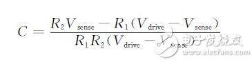
Where Vdrive and Vsense are complex variables.
Since the input signal is sinusoidal and periodic, its amplitude and phase information are stored in the real and imaginary parts, respectively. Performing DFT on Vsense provides the necessary information about the capacitance variation.
4. Actual Circuit Design for Detection Interface
Due to the variety of capacitive sensors and the wide range of capacitance values, it is essential to select appropriate components based on the specific measurement range to implement the proposed detection principle. Proximity capacitive sensors are commonly used and consist of three plates: one part of the human body (such as a finger) acts as a movable plate, while the other two are fixed. One block is excited with a constant sinusoidal voltage, and the other is grounded. When the human body approaches, the capacitance increases, and once a certain threshold is exceeded, the presence of the body is detected. The core of the sensor lies in the accurate detection of micro-variable capacitance. Based on the above principle, an actual circuit has been designed to achieve this goal.
Earth anchors are used in a variety of applications including:
- Retaining wall reinforcement
- Temporary structural support for buildings and tents
- Secured tie down anchorage for floating docks and pipelines
- Utility pole and tower anchors
- Erosion control anchoring
Earth Anchors,M22 M16 Stay Rod Anchor,Galvanized Steel Rod,Hdg Adjustable Anchor Rod
Shahe Yipeng Import and Export trading Co., LTD , https://www.yppolelinehardware.com