This article discusses the key points of software and hardware development for embedded handheld devices such as mobile TV: how to design hardware, achieve audio and video synchronization, improve H.264 decoding rate, and prevent DMA buffer overflow.
hardware design
Hardware design overview
The choice of hardware configuration should be considered comprehensively. For example, the processing function of the CPU is related to the final decoding display effect. Of course, choosing some high-end general-purpose processors or dedicated media processors can achieve better results, but it increases the cost of hardware. You can take a compromise on the final display effect and hardware selection. At present, there are not many chips that can receive T-DMB and DVB-H standards. You can choose some mainstream chips on the market. The hardware configuration of this product discussed in this article is: S3C2440A (400MHz), 64MB SDRAM, apollo fs1110, kino2efs1026. Can basically meet the hardware requirements of mobile TV. The radio frequency signal received through the antenna is sent to the RF tuning chip APOLLO FS1110 at the front end of the radio frequency. The main function is to demodulate the radio frequency signal into an IF (Intermediate Frequency) signal. This chip is the mainstream product currently on the market, can receive multiple standard signals, and small size (5.0mmx5.0mmx0.9mm), low power consumption (80mW), has three low-noise front-end amplifiers, covering L-Band , Band â…¡ and Band â…¢ three frequency bands. apollo fs1110 sends the IF signal to kino2 efs1026 to complete the source code decoding and output MPEG2-TS data. kino2 is a highly optimized baseband processor, small size (10mm & TImes; 10mm & TImes; 1.3mm), low power consumption (100mW), can provide various DMB code rates, up to 1.8Mbps, on-chip RS decoder, can Achieve better mobile channel performance. Kino2 sends the source TS stream to the CPU, and the CPU completes the demultiplexing, decoding, and display of the TS stream. The hardware design block diagram is shown in Figure 1.
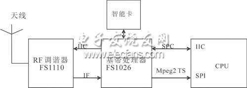
Figure 1 Block diagram of hardware design
Description of hardware function modules
Mobile TV terminals must eventually support multiple standards and multiple frequency bands, which is also the market demand. Because the frequency bands used by the three places that carry out mobile TV services are not the same, for example, Beijing and Guangdong use VHF Band 3, and Shanghai uses L-Band. Therefore, if the same mobile TV terminal wants to receive mobile phone services in different regions of the country , Need to support multiple bands. The working frequency band adopted by T-DMB discussed in this article is VHF 3 band and L band. Therefore, Band III and L-Band of FS1110 should be used; Band II is mainly used for FM broadcasting. The three high-frequency inputs of FS1110 can be used. The frequency band selection can be controlled by FS1026 through the IIC interface. At the same time, the initialization of the internal registers of FS1110 is also completed through this interface.
The downstream FS1026 baseband processor module receives the IF signal from the RF tuner, and finally completes the source decoding. The output MPEG2-TS data supports both parallel and serial formats. Serial data can be directly connected to the CPU through the SPI interface. The baseband module can also exchange control information with the CPU through the SCP (Serial Control Port) interface. The SCP interface and the IIC interface are fully compatible. You can also use the serial port (UART) to communicate with the CPU. Because some commercial DMB programs are scrambled (encrypted) by the service provider, the smart card module can complete the descrambling function.
The function of the CPU is to receive TS data through the SPI interface and display after decoding the audio and video. Data can be buffered by DMA, and then data can be read from DMA for demultiplexing. The DMA mode is a high-speed data transfer operation that allows direct reading and writing of data between external devices and memory, neither through the CPU nor CPU intervention. The entire data transfer operation is performed under the control of the DMA controller. In addition to the CPU doing a little processing at the beginning and end of data transfer, the CPU can perform other tasks during the transfer. Thus, most of the time, the CPU and input / output are in parallel operation. Therefore, the efficiency of the entire system can be greatly improved. Under the WinCE platform, the operation of DMA is quite convenient, and the development of the driver is not difficult. Reading data is like operating an ordinary file. The only difference is to prevent DMA overflow. Because the reading of ordinary files is completely controllable, and here is dealing with a "real-time" stream, overflow may occur. Overflow includes overflow (data read too slow) and underflow (read too fast). The principle of preventing data overflow at the receiver end of the MPEG decoder is the same, mainly because the image encoding format is different, and the data rate of the front end of the transmitted decoder is not constant. MPEG uses flow rate feedback control to control data overflow, so that the data rate reaching the audio and video decoder tends to be constant. The control of DMA is simpler. A dedicated thread is used to read data, and the demultiplexing thread can discard some frames or slow down the decoding speed according to the amount of data. However, there are still many cases of frame loss.
Hardware design considerations
The main problem when designing the hardware circuit is high frequency and electromagnetic compatibility. The general method is to add a shield. You can add a shield to the APOLLO FS1110 to reduce the spatial interference of the module. Of course, APOLLO FS1110 and KINO2EFS1026 can also be made as external modules. You can also reduce the effects of high frequencies by optimizing the design of the schematic. Because the quality of the schematic directly affects the difficulty of layout and wiring, and the performance of the board in the future. In order to clearly design the partition when placing and routing, in order to reduce the influence between each functional module, the digital, analog and RF circuits should be separated when designing the schematic diagram. However, due to the small size of handheld devices, shields are generally essential.
software design
T-DMB standard overview
T-DMB adopts H.264 video compression standard, audio adopts MPEG-4 bit-sliced ​​arithmetic coding BSAC (Bit-Sliced ​​ArithmeTIc Coding) or AAC + (adopted by European T-DMB) with lower patent fee, and the image format is CIF (Common Intermediate Format) (352 & TImes; 288), add some user data to these audio and video streams, after MPEG-4 SL (Sync Layer) synchronization layer packaging and MPEG-2 TS (Transport Stream) multiplexing, it is handed over to the modulation The modulator is modulated to transmit the signal suitable for propagation on the channel. The receivers of various standards have great differences except for channel decoding, and the source decoding is very similar. The structure of the encoder at the sending end of the T-DMB system is shown in Figure 2.
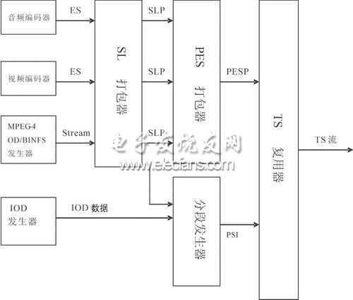
Figure 2 T-DMB transmitter block diagram
The MPEG-4 OD / BINFS generator generates audiovisual objects, scene space-time relationship information and audiovisual object descriptor information. The IOD generator generates the initial information of audiovisual objects: scene description and object description information. The segment generator mainly collects SLP and IOD data information, which is used to generate PSI (Program Specific Information) related to program demultiplexing. In the data stream of T-DMB, the IOD_descriptor can be obtained by parsing the description field in the PMT, and the scene and object description information can be obtained from the IOD_descriptor. Information such as ES_descriptor can be obtained from the object description. SL Synchronization Packer is mainly responsible for the synchronization of audiovisual objects and auxiliary data. After the SL packet is packed by PES, the PES packet is sent to the modulator as a TS packet.
We offer Phone Glass Protector, iPhone Glass Screen Protector, Tempered Glass for iPhone
Features:
|
Feature |
Thickness: 0.33mm |
|
Hardness: 9H |
|
|
Anti-oil, easy absorption |
|
|
Super high-definition for true color display, enjoy your visual feast |
|
|
Our cell phone protective films can anti-smudge and anti-fingerprints protection |
|
|
Anti-scratch and explosion-proof |
|
|
Provide supreme and nice appearance , our tempered glass protector make people feel comfortable and smooth grip |
|
|
Bubble-free and easily absorb |
|
|
Lead time |
7-9 working days/ Sample lead time : 1-4 days |
|
Package |
crystal boxes and Blister box packing available |
|
Payment |
T/T, Western Union, L/C, PayPal |
Glass Screen Protector
Glass Screen Protector,Tempered Glass Screen Protector,Anti Fingerprint Glass Screen Protector,Iphone 6 Plus Screen Protector,Iphone 6 Screen Protector,Iphone 6S Screen Protector,Iphone Glass Screen Protector,Tempered Glass For Iphone
Hebei Baisiwei Import&Export Trade Co., LTD. , https://www.baisiweicable.com