With the increase of electronic systems in automobiles, how to conduct highly efficient testing of highly mechatronic vehicle systems is a challenge faced by Chinese test engineers. As this article addresses the various testing issues involved in the automotive development process, please ask Yokogawa Introduce a complete solution to meet the needs of engine, drive, vibration, environmental impact, fuel cell efficiency and CAN bus testing.
I. Introduction
With the development of the automobile industry and the electronics industry, more and more electronic technologies are applied to modern automobiles. Automobiles will also develop from simple mechanical products to advanced mechatronic products. Due to the popularity of real-time driving information systems and multimedia devices in automobiles, automobiles are more personalized, versatile, safe and comfortable. The rapid development of wireless and mobile computer technology, even if driving alone in strange land, will not feel lonely or disoriented. In people's lives, cars are not just tools for transportation, but gradually become a way to enjoy life. Research in the field of automotive electronics has become the most active part of automotive research and development, and the results achieved in this area will achieve greater returns in the market.
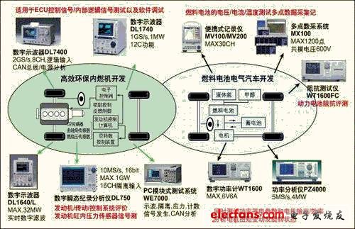
This article introduces the various test solutions provided by Yokogawa for the engine analysis, drive analysis, vibration analysis, environmental impact, fuel cell efficiency analysis, CAN bus analysis and other aspects involved in the automotive development process (Figure 1).
2. Testing of electric vehicle fuel cells
For engineers engaged in automotive R & D, the following aspects in testing are important factors that affect test efficiency and results:
(1) Various high-frequency and low-frequency, high-power and low-power electromagnetic radiation interference (2) Common-mode electrical pressure, vibration, and variable environment (3) Reliability of data collection and analysis (4) Instrumentation during road test Power supply and energy consumption (5) Easy to move and use on site
Through communication with test engineers of automobile production R & D companies, Yokogawa continues to improve its products to make it more suitable for the needs of automobile research and development. For example, in order to meet the research needs of electric vehicle fuel cells, Yokogawa developed the DAQMaster series MX100 based on the DARWIN series.
Because each battery only outputs 0.8-1.5VDC, in order to output enough power. The fuel cell stack generally consists of about one hundred monolithic batteries, especially for automotive applications, and the battery pack will consist of six hundred monolithic batteries. The battery voltage monitoring (CVM) system can detect problematic batteries by testing the voltage of each monolithic battery in the battery pack structure; analyze the battery performance in the field or under long-term operation with load.
Use differential input when detecting battery voltage. Although the voltage of the single-chip battery is not high, the differential input terminal generates a voltage of several hundred volts to the ground terminal of the test instrument. This voltage is called the common-mode voltage. Most data acquisition instruments (DAQ) have no insulation, and the input voltage limit is generally 5 volts or 10 volts. In addition, non-insulated instruments are often easily affected by ground loops. In order to overcome the problem of high common mode voltage in the fuel cell CVM system, high voltage insulation is required. Although external signal converters or buffers can be used, in order to reduce the size and cost while ensuring higher signal resolution and accuracy, many DAQ systems now have built-in buffers.
MX100
DAQMaster can provide the highest level of channel-to-ground isolation between modules and channels. In addition, its modular structure and standard software make it easy to monitor the battery voltage of up to 1200 channels.
The design of a DAQ system that simultaneously achieves high-voltage insulation and multiple channels is a challenge because most data acquisition instrument modules use a single AD converter in combination with front-end multiplication or scanning. The high common mode voltage signal must pass through the switching relay before being insulated and discretized by the insulation transformer and AD converter.
The MX100 uses Yokogawa's patented high-voltage solid-state semiconductor relay in the scanner to achieve multi-channel input signal switching. This relay is composed of high-voltage (1500VDC) and low leakage current (3nA) MOSFET Field Effect Transistor) and voltage output photocoupler, which has the advantages of 10-channel high-speed scanning within 1 second period, no contact, long life and no noise.
In addition, the insulation transformer and integral AD converter inside the MX100 are also Yokogawa's patented technologies. Other DAQ systems that use electromagnetic relays to provide insulation will have problems with switching time, switching stability, and daily maintenance. Finally, MX100 DAQMaster provides high-performance insulation and 4-channel simultaneous sampling, because the hardware of each channel of the 4-channel module is composed of independent hardware.
For correct waveform reproduction, the sampling rate is very important, high-speed acquisition can get the correct data. For this MX
The minimum measurement period of 100 is 10ms, and 3 measurement periods can be mixed in a system. The measurement period can be set individually for each module. The MX100 supports a CF card with a maximum capacity of 2G Bytes, and starts data backup when communication fails. When the communication returns to normal, data transfer to the PC is automatically restarted. The MX100's high-speed / multi-channel / high withstand voltage / multi-cycle characteristics for fuel cell testing help test engineers improve the efficiency and accuracy of testing.
3. CAN bus analysis
Car bus technology is widely used in today's cars. The automobile bus provides a unified data exchange channel for various complex electronic devices, controllers, and measuring instruments in the automobile. The number of components controlled by the electronic control unit (ECU) on the car is increasing, such as electronic fuel injection devices, idle speed control (ISC), anti-lock brake devices (ABS), airbag devices, electronic door and window devices, active Suspension, etc. With the widespread application of integrated circuits and single-chip microcomputers in automobiles, the number of ECUs in vehicles is increasing.
As a result, a new concept-the concept of CAN on the vehicle controller network came into being. CAN is the earliest data communication protocol developed by the German BOSCH company to solve the data exchange between the control and test instruments in modern cars. According to the relevant standards of ISO, the topology of CAN is bus, so it is also called CAN bus .
With the widespread use of the CAN bus, the testing and analysis of bus signals have become increasingly important in all aspects of automotive R & D, production, and maintenance, especially the observation and analysis of noise signals.
Abnormal phenomena such as reflected noise caused by cable wiring length, terminal impedance position, or overload LEVEL variation when connecting multiple contacts, can be triggered by the CAN signal of the DL7400 series to capture the CAN bus signal and display its waveform. The analysis according to the CAN protocol is displayed together with the waveform signal in the form of a list. The trigger condition can be set to the field or multiple fields of the CAN data frame (ID, Data, RTR bits, etc.). Trigger can also be activated in error frame. The captured CAN bus waveform data can be analyzed on the time axis, and the ID and data of each frame are displayed in hexadecimal or binary symbols.
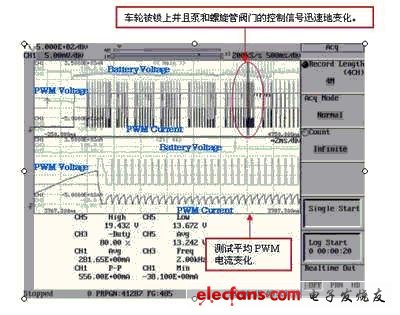
4. Battery voltage fluctuations during ABS operation
The ABS control device monitors whether the wheels are locked by comparing the signals from the speed sensors attached to each wheel. When the ABS control device detects that a wheel is locked, it sends a signal to the ABS transmission to open the valve. ABS transmission device includes solenoid valve, pump, motor, brake fluid tank. Opening the valve can instantly reduce the disc hydraulic pressure, weaken the braking force, and restore the wheel speed.
Then quickly increase the disc hydraulic pressure again and increase the braking force through the ABS transmission. In other words, the brake can be prevented from being locked by increasing or decreasing the disc hydraulic pressure. Increasing the disc hydraulic pressure is to use the pump to press the liquid into the cylinder, which will make the pump motor work quickly. This fast motor will affect the PWM current signal that controls the solenoid valve. General ABS operation cannot determine whether this affects battery voltage fluctuations. Therefore, it is necessary to observe this battery voltage fluctuation.
Using DL750 Max.1GW long memory can sample and capture all the braking action process from the beginning to the end at high speed. You can also use the zoom function to test one of the irregular parts in detail after capturing the overall process. This function can automatically set the automatic test area of ​​the waveform parameters, including the enlarged area. This zoom function can not only accurately test the irregular part of a cycle but also automatically test the waveform parameters in the zoom area.
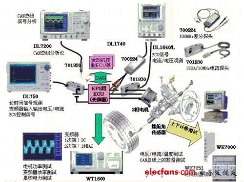
V. Development of power steering wheel control ECU (including inverter) / motor
The power steering wheel (EPS) has been widely used in small cars, but it needs to use a 3-phase motor when it is used in large vehicles that require large torque. Unlike traditional DC machines, testing a 3-phase AC motor requires a power meter to test power and Efficiency. In addition, the CAN bus communication between ECUs must also test the CAN bus signal.
DL7400 can trigger specific ID / Data on the CAN bus to realize synchronous observation with other signals. The general-purpose oscilloscope DL1640 / DL1740 can test the CPU signal of the ECU. The 100MHz differential probe and 150A current probe can also test the inrush current of the motor. The DL750 has up to 16ch of insulated input, which is suitable for long-term observation of inverter input / output voltage / current and ECU control signals.
WT1600 can evaluate the primary-side DC and secondary-phase 3-phase current / voltage / power of 3-phase drive system inverters for large-scale automotive EPS, and the efficiency of the inverter. Cumulative power testing can also be performed for specific operating modes. Using WE7000's time module / CAN module / isolated A / D module / temperature module can realize multi-channel comprehensive test. Steering angle / consumption current / voltage / temperature and other multi-channel simultaneous test for a long time. Using the CAN module can simultaneously convert the data on the CAN bus into physical quantities to achieve simultaneous testing.
6. Direct injection diesel engine injection experiment
Direct injection diesel engines can reduce fuel costs and purify exhaust emissions. The following is a solution to the performance evaluation method of high-pressure injection and electronic control, the key to its development:
(1) Evaluation of design values ​​of mechanical parts (injection time and injection pressure)
The test objects are the injection pressure of the fuel injected by the nozzle, the engine speed change and the opening and closing time of the nozzle solenoid valve. Engine development requires dynamic testing (gradually increasing the engine speed to check whether it meets the design requirements) and static testing (checking whether the operation is stable at a fixed speed).
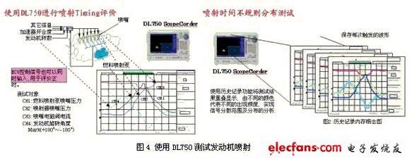
(2) Synchronous test with ECU control signal
Synchronous test with ECU control signal to test ECU timing and actual injection timing.
7. Summary of this article
Due to extensive cooperation with vehicle and component companies around the world, Yokogawa has many test cases in this field. Yokogawa hopes to contribute to the development of automotive electronics.
The Transient Voltage Suppressor (TVS) is a high-performance protection device in the form of a diode. When the two poles of a Tvs Diode are subjected to a reverse transient high-energy shock, it can change the high impedance between the two poles to a low impedance at a speed of the order of 10 minus 12 powers, absorbing up to several kilowatts of surge power. The voltage between the two poles is clamped to a predetermined value, effectively protecting the precision components in the electronic circuit from various surge pulses.
Transient Voltage Suppressor
Transient Voltage Suppressor,Tvs Diode,Tvs Diode Ethernet,Tvs Diode For Automotive
Dongguan Agertech Technology Co., Ltd. , https://www.agertechcomponents.com