In small current grounding systems, the identification of single-phase ground faults and the suppression of ferroresonance are key research areas. The "S injection method" has proven effective in addressing these issues. This technique involves injecting a special signal current into the system during a ground fault, allowing for accurate line selection through signal tracking. The TY series line selection protection, based on this principle, has been widely implemented in domestic power systems, achieving successful results. Ferroresonance, often caused by resonance between the excitation reactance of potential transformers (PTs) and the system's distributed capacitance, can be mitigated by adjusting the PT wiring. However, such modifications might interfere with the "S injection method."
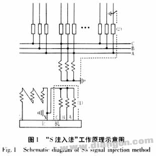
The "S injection method" was introduced in 1993 as a novel approach for single-phase grounding detection in small current systems. It works by injecting a specific signal current into the system when a ground fault occurs, using the tracking principle to identify the faulty line. The injected signal operates at a frequency between the nth and (n+1)th harmonic of the power frequency. A schematic is shown in Figure 1.
Under normal conditions, all phase voltages (UAN, UBN, UCN) are 57.7V, and the zero-sequence voltage (ULN) is 0V. When a single-phase ground fault occurs, such as in phase A, UAN drops to 0V, while UBN and UCN rise to 100V. The system detects this change and injects a signal current into the grounded phase. This current flows along the faulted line and returns to ground. Only the faulty line carries this signal, enabling precise fault location through tracking.
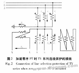
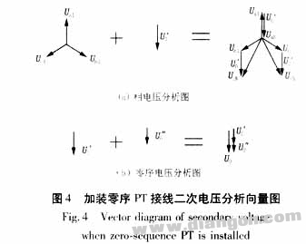
In practice, the TY series protection often uses special PT wiring configurations, such as the addition of a zero-sequence PT. This setup creates a 3n-order harmonic path, reducing zero-sequence impedance. The wiring is illustrated in Figure 2. During normal operation, only positive sequence voltages exist. When a single-phase ground occurs, the system decomposes the voltage into positive and zero-sequence components. The vector diagram (Figure 3) shows that both components have equal magnitude.
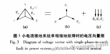
During a ground fault, the zero-sequence PT measures the zero-sequence voltage, which is three times the base value. This configuration helps avoid resonance between the system’s distributed capacitance and the busbar. Both standard and zero-sequence PT wiring achieve similar performance in terms of phase voltage monitoring but differ in their handling of zero-sequence voltages and harmonic suppression.
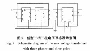
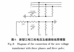
Recently, Jiangxi Transformer Factory introduced a combined system using three-phase three-column PTs and a single-phase zero-sequence PT, as shown in Figure 5. This configuration eliminates the need for an external zero-sequence PT, simplifying wiring while providing effective harmonic suppression. The primary PT has a ratio of 10kV/100V, and the zero-sequence PT has a ratio of 10kV/100V/√3. The core’s infinite zero-sequence reluctance ensures no need for short-circuiting, as shown in Figure 6.
![]()
![]()
The new PT design simplifies the installation process and enhances system reliability. It effectively suppresses harmonics while maintaining compatibility with the "S injection method." This integration improves the overall performance of line selection and fault detection in power systems.
Conclusion: The "S injection method" relies on PT-based signal injection, making PT wiring configurations critical. Both analyzed wiring methods support the "S injection method" and offer additional harmonic elimination capabilities, proving their effectiveness in modern power systems.
KW4-Micro Switch Quick Connect Terminal
quick connect terminal micro switch,Basic Micro Switch,Quick Connect Terminal 2 Pin
Ningbo Jialin Electronics Co.,Ltd , https://www.donghai-switch.com