1. Foreword Our company is a pharmaceutical company that mainly produces hepatitis B vaccine. The purification of the central air-conditioning equipment provides a clean environment for the production workshop, so that the temperature, humidity and pressure difference of each room in the production workshop can meet the requirements of the national GMP regulations. Due to seasonal changes, day and night changes, each room in the production workshop has a significant change in demand for air volume, and the air volume and water flow of the pump fan are adjusted by manual adjustment of the air door and throttle valve. When the demand for air volume and water flow decreases, the opening of dampers and valves decreases; when the demand for air volume and water flow increases, the opening of dampers and valves increases. Although this adjustment method is simple and easy to use, it has become a habit, but it is at the cost of increasing the loss of the pipe network and consuming a large amount of energy on the dampers and valves. Moreover, when the central air conditioner is working normally, the opening of most dampers and valves are between 50% and 60%, which shows that the design capacity of the existing central air conditioner water pump fan is much higher than the actual need, and there is a serious The phenomenon of "car" causes a lot of waste of electrical energy. In recent years, with the rapid development of electric power, electronic technology, and computer technology, the frequency conversion speed regulation technology has become more and more mature. Therefore, we have installed 19 frequency converters for the company's central air conditioning water pump fan for energy-saving transformation. In addition, due to the greater dispersion of pumps and fans, in order to reduce the intensity of the patrolling work of the duty personnel, it is convenient to grasp the working status of the pumps and fans and find faults in a timely manner, we use PLC and human-machine interface to communicate with the inverter, and add them to the central monitoring room. Frequency conversion monitoring system, so that the staff on duty can directly set the frequency value and start and stop each inverter on the man-machine interface, which can monitor the actual working current, voltage and frequency of the pump fan motor in real time, and have alarm and other functions.
Second, the frequency conversion transformation plan of the central air-conditioning pump fan 1. The condition of the equipment before the transformation (1). The condition of the air-conditioning equipment of the genetic department ①The refrigeration host is a Hitachi unit, a total of three. ②Refrigeration pump: 11KW, 2 poles full pressure start 4 sets, head 30m, outlet temperature 6 ℃, return water temperature 10 ℃, outlet pressure 0.35Mpa, rated current of each motor 21.8A, normal working current 16.6A . Under normal circumstances, open two to prepare two. ③Cooling pump: 15KW, 2 poles full pressure start 4 sets, head 30m, outlet water temperature 32.5 ℃, return water temperature 28.2 ℃, outlet water pressure 0.38Mpa, rated current of each motor 29.9A, normal working current 18.0A . Under normal circumstances, open two to prepare two.
(2) Air conditioner equipment in the second-floor air-conditioning machine room ①The main cooling unit is a Hitachi unit, a total of two. ②Refrigeration pump: 15KW, 2 poles full pressure start 3 sets, head 30m, outlet water temperature 6.1 ℃, return water temperature 9.8 ℃, outlet water pressure 0.36Mpa, rated current of each motor is 29.9A, normal working current is 21A. Under normal circumstances, open one and prepare two. ③Cooling pump: 15KW, 2 poles full pressure start 3 sets, head 30m, outlet water temperature 31.8 ℃, return water temperature 27.7 ℃, outlet water pressure 0.41Mpa, rated current of each motor 29.9A, normal working current 20.6A . Under normal circumstances, open one and prepare two.
(3) Air conditioning equipment in sub-packaged air-conditioning equipment rooms ①The refrigeration main unit is a Hitachi unit, a total of two. ②Refrigeration pump: 15KW, 2 poles full pressure start 3 sets, head 30m, outlet water temperature 5.8 ℃, return water temperature 9.3 ℃, outlet water pressure 0.38Mpa, rated current of each motor 29.9A, normal working current 20.2A . Under normal circumstances, open two to prepare one. ③Cooling pump: 15KW, 2 poles full pressure start 3 sets, head 30m, outlet temperature 31.6 ℃, return water temperature 27.3 ℃, outlet water pressure 0.40Mpa, rated current of each motor 29.9A, normal working current 21.2A . Under normal circumstances, open two to prepare one.
(4) The company has 13 air-conditioning fan cabinets. â‘ There are 7 air conditioner fan cabinets in the Gene Department, including 3 22KW fan motors, 2 11KW fan motors, and 1 each of 15KW and 18.5KW fan motors. â‘¡ There are 3 air conditioner fan cabinets on the second floor, including 2 15KW fan motors and 1 11KW fan motors. â‘¢ 3 air conditioner fan cabinets in the Quality Inspection Department, including 2 11KW fan motors and 1 7.5KW fan motor.
2. The frequency conversion transformation scheme of the water pump is because the temperature difference between the inlet and outlet water of the refrigeration pump and the cooling pump is less than 5 ℃, which means that there is still a margin for the flow of chilled water and cooling water. In addition, the normal working current of the motor is less than the rated current (5-12A). Obviously, there is the phenomenon of "big horse-drawn carriage". Therefore, we use one Delta VFD-P11KW inverter and one Delta VFD-P15KW inverter for the chilled water system and the cooling water system of the Gene Department respectively to implement one drive and three drives (as shown in Figure 1). According to the need, PLC1 controls 3 chilled water pumps and 3 chilled water pumps in turn (but one inverter can only drive one pump motor at the same time), so that the chilled water volume and cooling water volume are flexible, convenient, timely and appropriate Automatic control to meet the needs of the production process. Similarly, one Delta VFD-P15KW inverter is used for the chilled water system and cooling water system of the old second-floor air-conditioning machine room and sub-package air-conditioning machine room. The cooling water system control method is the same. The following is a description of the chilled water system of the Gene Department:
(1) Closed-loop control The chilled water system of the Gene Department adopts full-closed automatic temperature difference control. A 11KW inverter is used to implement one for three. The specific method is: first open all the air valves of the central air-conditioning pump system completely, and on the premise of ensuring the chilled water volume and pressure of the refrigeration unit, determine the minimum working frequency of a refrigeration pump inverter (35HZ during commissioning). It is set to the lower limit frequency and locked. Use two temperature sensors to collect the temperature of the outlet water and return water on the main pipe of chilled water, send the temperature difference signal of both to the temperature difference controller, and adjust the temperature difference into analog quantity feedback to the inverter through PID2 adjustment, when the temperature difference is less than or equal to the set value At 5 ℃, the chilled water flow can be reduced appropriately. At this time, the VVVF2 frequency converter runs at a reduced frequency, and the motor speed slows down. When the temperature difference is greater than the set value of 5 ℃, the VVVF2 frequency converter runs at an increased frequency. increase. The working number and increase / decrease of the refrigeration pump are controlled by PLC1. In this way, according to the real-time needs of the system, the appropriate flow rate can be provided without causing waste of electric energy.
(2) Open-loop control Turn the transfer switch on the control screen to the open-loop position and turn the potentiometer clockwise to change the speed of the chilled water pump motor.
(3) The power frequency / frequency conversion switch works in the automatic working state of the system. When the inverter fails, another standby pump motor is controlled by PLC1 to be put into power frequency operation, and an audible and visual alarm is issued to remind the duty personnel to find and Handle the fault. You can also set the manual / automatic switch on the control cabinet panel to the manual position and press the corresponding start button to start the corresponding pump motor.

Figure 1 The principle diagram of frequency conversion transformation of central air conditioning pump
3. The frequency conversion transformation plan of the fan Because all the fans of the wind cabinet are in the fully open and normal load operation state, when the constant temperature is adjusted, the air volume is adjusted by the cold air outlet valve. If the temperature in the production workshop room is too high, the air valve is opened to increase the amount of cold air, which reduces the temperature in the production workshop room. If the temperature in the production workshop room is low, it is necessary to close part of the opening of the air valve to reduce the amount of cold air to maintain the cold and heat balance of the production workshop room. Therefore, the air volume sent into the production workshop is adjustable and variable. Especially during the night shift, there are few people, and there are few activities such as going in and out, walking, etc., the system load is very light, and the requirement for air conditioning cooling capacity is greatly reduced. Only a small amount of cold air can maintain the positive pressure and There is a demand for cooling capacity, so all of the 13 fans have been converted into energy-saving inverters, and inverters are used to adjust the air volume.
The principle diagram of frequency conversion transformation of the central air-conditioning fan is shown in Figure 2. On the basis of the original power frequency control, 7 frequency conversion control cabinets are added, and 13 Delta VFD-P series inverters are used to drive 13 fan motors. Frequency conversion / power frequency Can switch between each other. When running under the power frequency method, the original operation method is not changed. When running under the frequency conversion method, the inverter automatically outputs different frequencies in different time periods. That is, 13 inverters are controlled by the program of the time-controlled switch, and the inverters are set to run at 45HZ from Monday to Friday from 7:30 to 23:00, and from Monday to Friday from 23:00 to the next day. At 7:30 and Saturday and Sunday, set the inverter to run at 35HZ (the frequency of its operation can be set according to need) to change the speed of the fan. At the same time, 13 inverters and the man-machine interface of the central monitoring room and PLC implements online communication, which can realize remote man-machine monitoring.

Figure 2 Schematic diagram of frequency conversion transformation of central air conditioning fan
3. The effect of frequency conversion energy-saving transformation of central air-conditioning pump fan In order to visually reflect the energy-saving effect after frequency conversion transformation, we have done the following tests: 1 # Hitachi unit cooling water pump 14 # (15KW) and K4 wind cabinet 4 # (22KW) are For objects, install watt-hour meters on their respective main circuits, run at a power frequency for a week, record the meter readings every day, and then run for a week at the frequency conversion to perform the same work. The data is shown in Table 1 and Table 2.
Table 1: Statistics of energy saving data of 1 # Hitachi unit cooling water pump
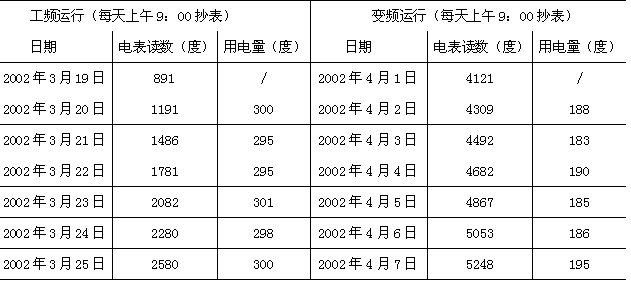
1. Data analysis of Table 1: During power frequency operation, the load change of the pump is not very large, and its daily power consumption is around 298 degrees. During frequency conversion operation, the daily power consumption varies greatly due to the external environment temperature, but it can be seen that the daily power consumption during frequency conversion operation is significantly smaller than the value at power frequency. We use one week's total power consumption to calculate, the power frequency is 2580-891 = 1689, and the frequency conversion is 5248-4121 = 1127, then the power saving rate of the cooling water pump of 1 # Hitachi unit is: (1689-1127) / 1689 = 33%
2. Data analysis of Table 2: As the load of the fan changes little every day, its power consumption is relatively stable. It can be seen that the daily power consumption is about 350 degrees when the power frequency is running. During frequency conversion operation, the daily power consumption is about 220 degrees. Calculated by 350 and 220, the power saving rate of K4 fan cabinet motor is: (350-220) / 350 = 37%
From the above calculation, we can see that the average energy saving rate of the frequency conversion of the pump and fan is 35%. In actual use, the power saving effect will be better.
Table 2: Statistics of energy saving data of K4 wind cabinet

4. Central air-conditioning pump fan frequency conversion monitoring system 1. System hardware composition The hardware structure diagram of the central air-conditioning pump fan frequency conversion monitoring system is shown in Figure 3. It consists of the company's tap water constant pressure pump, the second packaging refrigeration pump and the quality inspection department The four sub-systems of the water pump fan and the water pump fan of the genetic department of the old second floor air-conditioning machine room are composed of remote monitoring of 19 frequency converters distributed in different departments. The description of each part is as follows: ①The inverter selects Delta VFD-P series inverter, which has high reliability, low noise, high energy saving, sound protection function, and built-in powerful RS-485 serial communication interface And, RS-485 serial communication protocol is open to users and other characteristics. ② As the control unit, PLC is the control core of the entire system, and Delta DVP24ES01R is selected. Use its communication instructions to compile the program, download it to the PLC, and then connect it to the RS-485 serial communication interface of the inverter to realize real-time communication with the inverter. ③ The human-machine interface adopts Hitech's PWS-3760, color 10.4 inches. It is a new-generation high-tech programmable terminal, an interactive workstation specially designed for PLC. It has the connection monitoring capability with PLCs of various brands. It is suitable for applications in harsh industrial environments and can replace ordinary or industrial control computers. Its main features are: large screen capacity, up to 255 screens, simple screen planning; using ADP3 full Chinese operation software, suitable for WINDOWS95 / WINDOWS98 environment, rich macro instructions, simple programming; good interactivity, strong anti-interference ability , High communication reliability; high degree of automation, simple and convenient operation, low failure rate, long life, and low maintenance. Its main functions are: the designer can edit various screens according to the needs, and display the device status or system operation instruction information in real time; the touch buttons on the man-machine interface can generate corresponding switch signals, or input values ​​and characters to the PLC for data Exchange to generate corresponding motion control equipment operation; multiple screens can be overlapped or switched to display text, numbers, graphics, character strings, alarm information, motion flow, statistical data, historical records, trend graphs, simple reports, etc. ④, RS-485 serial communication method: RS-485 adopts balanced transmission and reception method, which has the advantages of long transmission distance, strong anti-interference ability and multi-station ability.
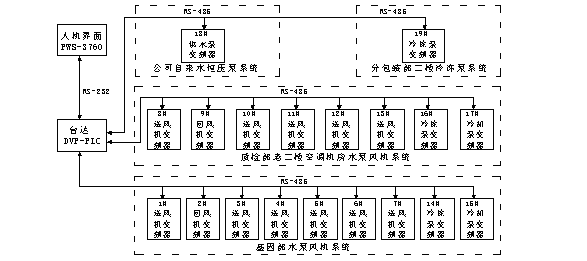
Figure 3 Hardware structure diagram of frequency conversion monitoring system
2. Man-machine interface screen design All the man-machine interface screens of this system are designed by ADP3 full Chinese software. There are main screen, parameter setting, operation setting, parameter display, status information, alarm information and help screen. After the software is compiled without errors, it can be used by downloading it from the personal computer to the display unit. The man-machine interface and PLC are connected by the master-slave method through an RS232 communication cable. The PLC reads and writes the status control area and the notification area of ​​the man-machine interface to achieve information interaction between the two. The PLC reads the data in the man-machine interface status notification area to obtain the current screen number, and writes the data in the man-machine interface status control area to force the screen switching. One of the parameter display screens is shown in Figure 4.
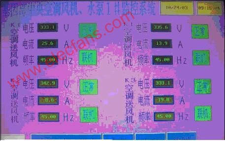
Fig. 4 Monitoring screen of central air-conditioning fan and water pump 1 # in the genetic department The user needs to monitor the voltage, current and frequency of 19 water pump fans. Therefore, three sets of numerical display areas are set for them, respectively displaying voltage, current and frequency values. This is achieved by using the numerical display function in the component. After the system is started, 19 frequency converters periodically reply to their working status to the PLC and send it to the man-machine interface after being processed by the PLC, so that the man-machine interface can display these three sets of values ​​in real time. The format, number of digits and precision of the value are set in the property box of the value display according to the actual situation.
3. System control method This system requires remote monitoring of 19 frequency converters distributed in different departments and at a distance. It can automatically / manually set, modify and write frequency values ​​and start on the man-machine interface of the central monitoring room. Stop each frequency converter, can monitor the actual working voltage, current and frequency of the central air-conditioning water pump fan motor in real time, and have functions such as sound and light alarm. The specific control method is: using a DVP-PLC, a man-machine interface PWS-3760 and 19 VFD-P series inverters to form a real-time communication network through RS-485 serial communication method (as shown in Figure 3), Set the communication parameters of 19 inverters on site, such as the control method is RS-485 communication instruction, communication address: 1-19, baud rate is 9600, communication data format, etc .; design system PLC program, program flow chart as Figure 5 shows. Requires manual control to have functions such as instant setting, modifying and writing frequency values ​​and starting and stopping each inverter. The automatic control adopts two period control, which can be set at any time with two period values ​​and corresponding two frequency values. Period value one: 7:30 corresponds to frequency one 45HZ, period value two: 23:00 corresponds to frequency two 35HZ. The program design refers to the VFD-P inverter communication protocol, and uses some RS-485 communication instructions between the PLC and the inverter to realize the remote monitoring of the system, and can also print the report through the printer.

Figure 5 System program flow chart
V. Concluding remarks The use of AC variable frequency speed regulators to carry out energy-saving transformation of the water pumps and fans of the central air-conditioning system, not only is simple and convenient to operate, saves electrical energy and reduces production costs, but also greatly improves the operating conditions of water pumps and fans, reducing water pumps, fans, valves, etc. Maintenance volume. This frequency conversion transformation project and monitoring system have been in continuous operation for more than two years since it was put into operation in May 2002. The system operates reliably and smoothly, the communication data is accurate and timely, standardizes equipment management, and improves work efficiency. The amount of online change required is the time period With the set value of frequency, the man-machine interface is used as a man-machine interaction tool, which is simple and intuitive and easy to operate. As the central processing unit, PLC is used together in the frequency conversion monitoring system, which realizes the system's remote monitoring, manual real-time frequency conversion and automatic time-division frequency conversion. It has achieved good results in actual use and is worthy of promotion to other industries. .
References 1. Mao Zhaohui. Application of PLC and Human Machine Interface in Frequency Conversion Monitoring System. Beijing. Journal of Electrical Engineering and Technology. 2004, 3
2. Delta Electronics Industry Co., Ltd. VFD-P series inverter user manual 3. Delta Electronics Industry Co., Ltd. DVP-PLC programmable controller instruction manual 4. Hitech Electronics Corp. PWS3760 installation instruction manual. 1999
5. Hitech Electronics Corp. Industrial-grade human-machine software ADP3 instruction manual. 1999
Xinxiang Mina Import & Export Co., Ltd. , https://www.mina-motor.cn